1 --- Reserved
2 --- Reserved
3 B Data line B (receive and send
line, positive)
4 --- Reserved
5 DGND Reference potential for data
transmissions and +5 V
6 VP (5 V) +5 V (Power supply voltage for
termination resistors)
7 --- Reserved
8 A Data line A (receive and send
line, negative)
9 --- Reserved
Shield Shield Shield, functional earth
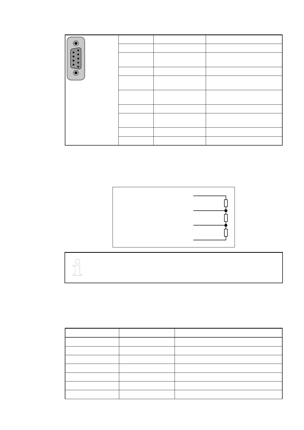
Bus Termination
The line ends of the bus segment must be equipped with bus termination resistors. Normally,
these resistors are integrated in the interface connectors.
390 Ohms
220 Ohms
390 Ohms
VP (+5 V)
GND (0 V)
RxD/TxD-P
RxD/TxD-N
Data Line B
Data Line A
6
3
8
5
The earthing of the shield should take place at the switch-gear cabinet, see
System Data AC500
Ä
Chapter 2.6.1 “System Data AC500” on page 1248.
Mounting on Terminal Units TU517 or TU518
The assignment of the terminals 1.0 - 1.9:
Terminal Signal Description
1.0 B Data line B (receive and send line, positive)
1.1 B Data line B (receive and send line, positive)
1.2 A Data line A (receive and send line, negative)
1.3 A Data line A (receive and send line, negative)
1.4 TermB Bus termination data line B
1.5 TermB Bus termination data line B
1.6 TermA Bus termination data line A
Communication Interface Modules (S500) > PROFIBUS
2019/04/17 3ADR010121, 13, en_US 945