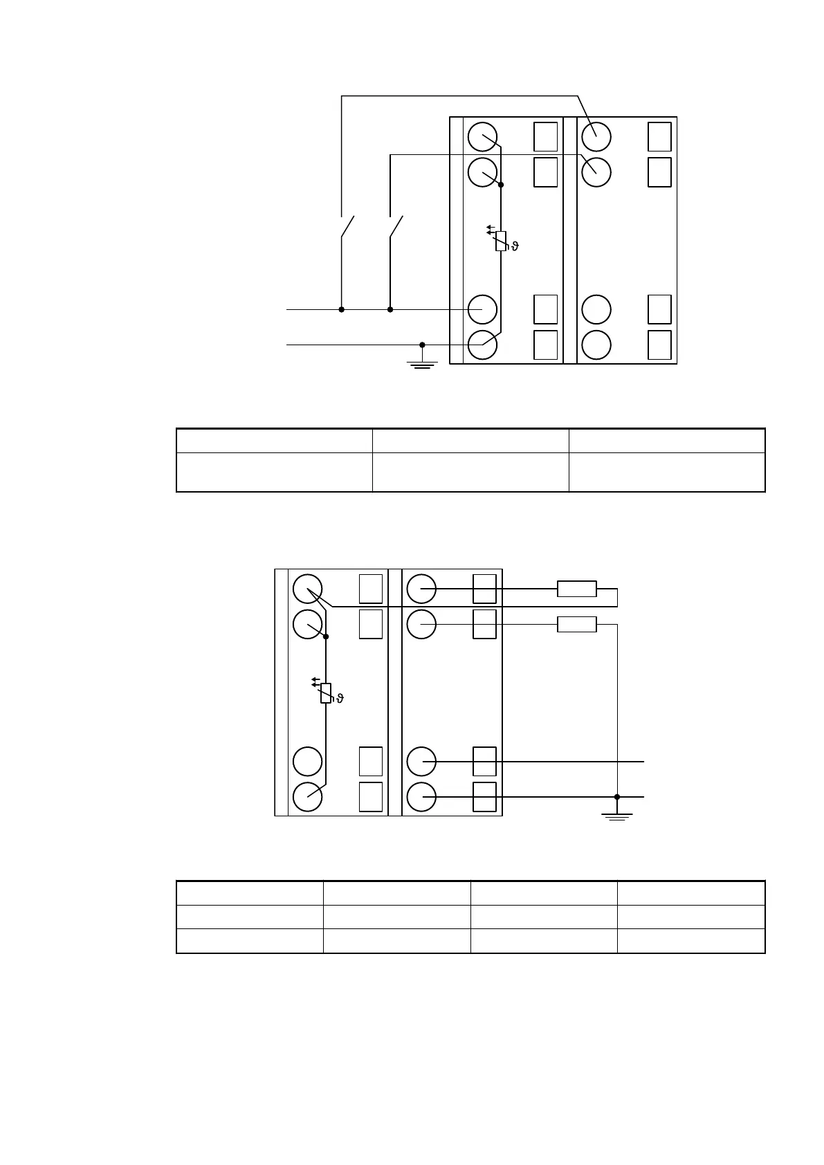
1.0
I0-
1.1
I1-
1.8
UP
1.9
ZP
PTC
2.0
I0+
2.1
I1+
2.8
UP
2.9
ZP
UP
ZP
Fig. 77: Connection example
Digital input 24 V 1 channel used
Effect of incorrect input ter-
minal connection
Wrong or no signal detected,
no damage up to 35 V
Connection of Analog Output Loads (Voltage, Current)
UP
ZP
3.0
O0-
3.1
O1-
3.8
UP
3.9
ZP
PTC
4.0
O0+
4.1
O1+
4.8
UP
4.9
ZP
-10 ... +10 V
0 ... 20 mA
4 ... 20 mA
Fig. 78: Connection example
Voltage -10 V...+10 V Load max. ±10 mA 1 channel used
Current 0 mA...20 mA Load 0 W...500 W 1 channel used
Current 4 mA...20 mA Load 0 W...500 W 1 channel used
Only the channels 0...3 can be configured as current output (0 mA...20 mA or 4 mA...20 mA).
Unused analog outputs can be left open-circuited.
I/O Modules > Analog I/O Modules
2019/04/173ADR010121, 13, en_US554