Important: The earthing potential at the sensors must not have a too big potential difference with
respect to ZP (max. ±1 V within the full signal range). Otherwise problems can occur concerning
the common-mode input voltages of the involved analog inputs
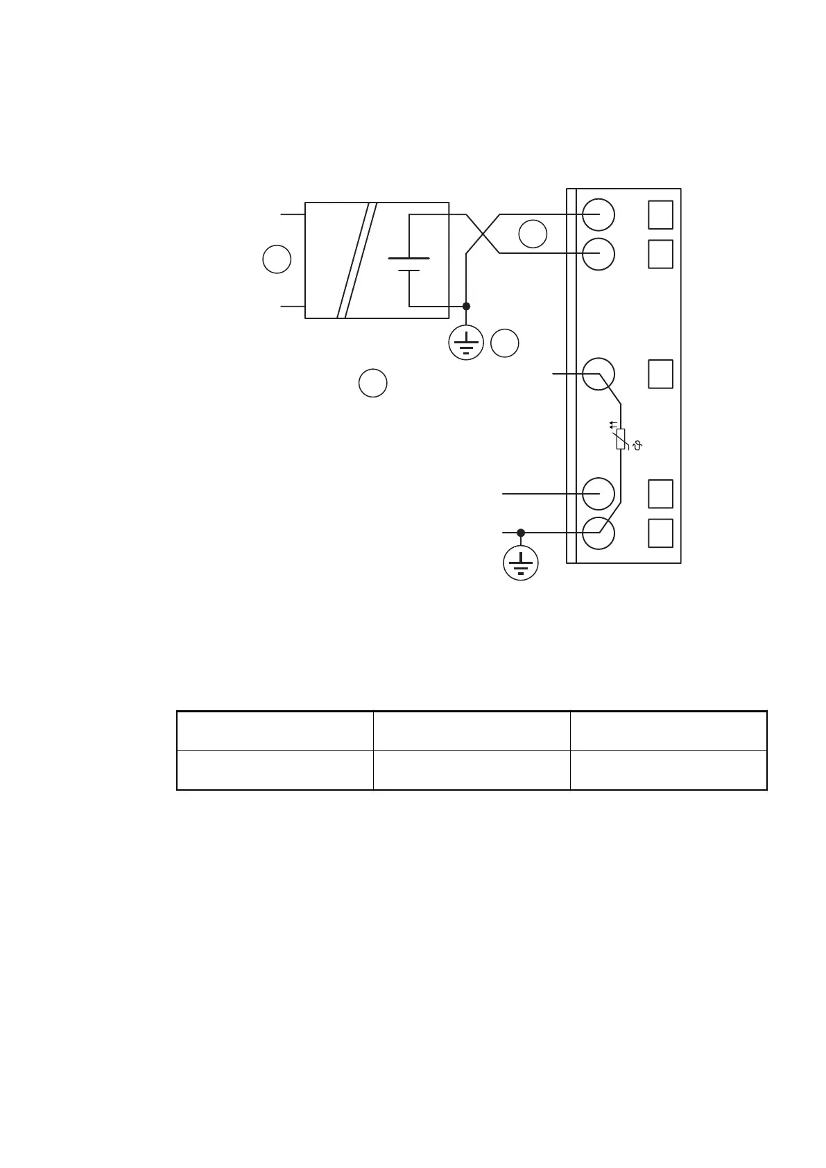
The following figure shows the connection of active-type analog sensors (voltage) to differential
inputs.
+
–
1.0
1.1
1.8
1.9
AI0+
AI1+
UP
ZP
UP
ZP
PTC
1.5
AI–
3
1
2
0...10 V
–10 V...+10 V
4
Fig. 166: Connection of active-type analog sensors (voltage) to differential inputs
1 1 analog sensor requires 2 channels
2 Electrically isolated power supply for the analog sensor
3 Earthing at the sensor
4 0 V...10 V / -10 V...+10 V connected to differential inputs
Voltage 0 V...10 V with differential inputs, 2 chan-
nels used
Voltage -10 V...+10 V with differential inputs, 2 chan-
nels used
The measuring ranges are described in the section Measuring Ranges
Ä
Chapter 1.7.3.1.7
“Parameterization” on page 842
Ä
Chapter 1.7.3.1.10 “Measuring Ranges” on page 851.
In order to avoid error messages or long processing times, it is useful to configure unused
analog input channels as "unused".
Use of Analog Inputs as Digital Inputs
Several (or all) analog inputs can be configured as digital input. The inputs are not electrically
isolated against the other analog channels.
The following figure shows the use of analog inputs as digital inputs.
Communication Interface Modules (S500) > EtherCAT
2019/04/173ADR010121, 13, en_US838