EasyManuals Logo

ABB AC500 PLC User Manual

ABB AC500 PLC
1315 pages
To Next Page IconTo Next Page
To Previous Page IconTo Previous Page
Page #42 background imageLoading...
Page #42 background image
NOTICE!
Risk of malfunctions in the plant!
A ground closure, e. g. caused by a damaged cable insulation, can bridge
switches accidentally.
Use sink inputs when possible or make sure that, in case of error, there will be
no risks to persons or plant.
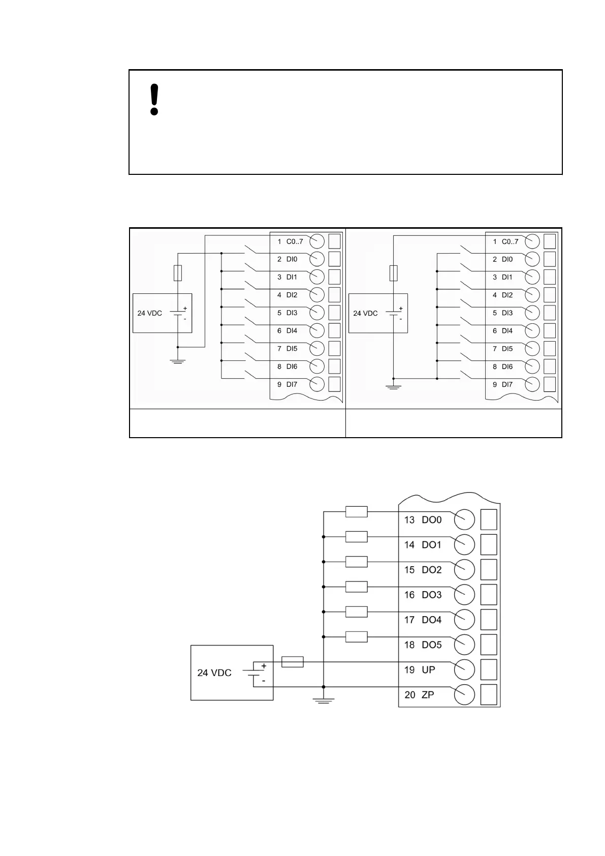
The following figure shows the electrical connection of the digital inputs to the PM55x processor
modules:
Electrical connection of digital inputs (sink
inputs)
Electrical connection digital inputs (source
inputs)
Connection of the Digital Transistor Outputs (PM55x-T(P) only)
Fig. 2: Electrical connection of digital transistor outputs
Device Specifications
Processor Modules > AC500-eCo
2019/04/173ADR010121, 13, en_US42

Table of Contents

Questions and Answers:

Question and Answer IconNeed help?

Do you have a question about the ABB AC500 PLC and is the answer not in the manual?

ABB AC500 PLC Specifications

General IconGeneral
Digital InputsUp to 1024
Digital OutputsUp to 1024
Real-time clockYes
Power Supply24 V DC
Protection ClassIP20
ProcessorARM based
Programming LanguagesIEC 61131-3 (LD, ST, FBD, SFC, IL)
Operating Temperature-25°C to +70°C
Communication InterfacesEthernet, CAN, RS-232, RS-485

Related product manuals