1
)
In AC500 the following interface identifier applies:
14 = I/O bus, 11 = COM1 (e.g. CS31-Bus), 12 = COM2.
The PNIO diagnosis block does not contain this identifier.
2
)
With "Device" the following allocation applies:
31 = module itself, 1...10 = expansion module 1...10, ADR = hard-
ware address (e. g. of the DC551-CS31)
3
)
With "Module" the following allocation applies dependent of the
master:
Module error: I/O bus or PNIO: 31 = module itself; COM1/COM2:
1...10 = expansion 1...10
Channel error: I/O bus or PNIO = module type (1 = AI); COM1/
COM2: 1...10 = expansion 1...10
4
)
In case of module errors, with channel "31 = Module itself" is output.
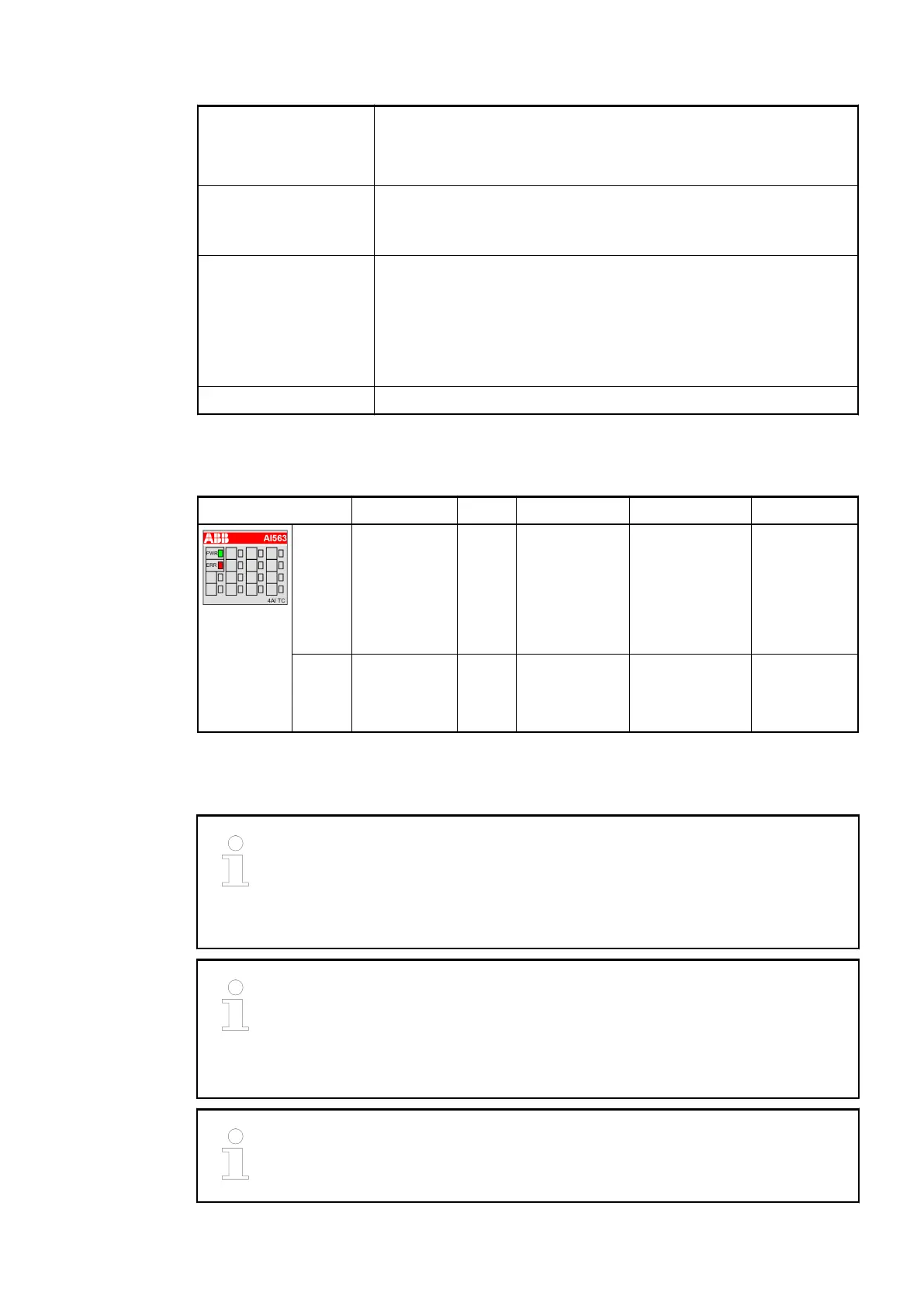
State LEDs
LED State Color LED = OFF LED = ON LED flashes
PWR Process
voltage
24 VDC via
terminal
Green CPU module
voltage or
external
24 VDC supply
voltage is
missing
3.3 V system
voltage (I/O
bus) and
external
24 VDC supply
voltage are
present
---
ERR Channel or
module error
Red No error or
process
voltage is
missing
Severe error in
the module
Error on 1 or
more chan-
nels of the
module
Measuring Ranges
AI563 needs 4 seconds for initialization after applying the process supply
voltage to clamp UP/ZP. During these 4 seconds, the measurement values are
set to '0'. After that, valid measurement values are provided by the module.
After an interruption of the process supply voltage > 10 ms, a re-initialization is
performed by AI563.
Risk of invalid analog input values!
The analog input values may be invalid if the measuring range of the inputs is
exceeded.
Make sure that the analog signal at the connection terminals is always within
the signal range.
When a wire break occurs on a sensor wire, the temperature measurement
value of the corresponding channel changes to Overflow (Hexadecimal 7FFF).
I/O Modules > Analog I/O Modules
2019/04/17 3ADR010121, 13, en_US 423