1.8.1.10.3 Connections
Pin No. Signal Description
1 Terminator P Terminator positive
2 RxD/TxD-P Receive/transmit positive
3 RxD/TxD-N Receive/transmit negative
4 Terminator N Terminator negative
5 FE Functional earth (internally
connected to DIN rail spring)
RS-485 communication requires an electrical termination of the communication line. The fol-
lowing is necessary:
● 2 resistors of 120 W each at both line ends (to avoid signal reflections)
● a pull-up resistor at RxD/TxD-P and a pull-down resistor at RxD/TxD-N. These 2 resistors
care for a defined high level on the bus, while there is no data exchange.
In every RS-485 network 1 pull-up and pull-down resistors must be activated. It is recom-
mended to activate the pull-up and the pull-down resistors at the bus master. These 2 resistors
are integrated inside the TK506 RS-485 isolator. They can be activated by connecting the termi-
nals 1-2 and 3-4 of the terminal block with cable bridges.
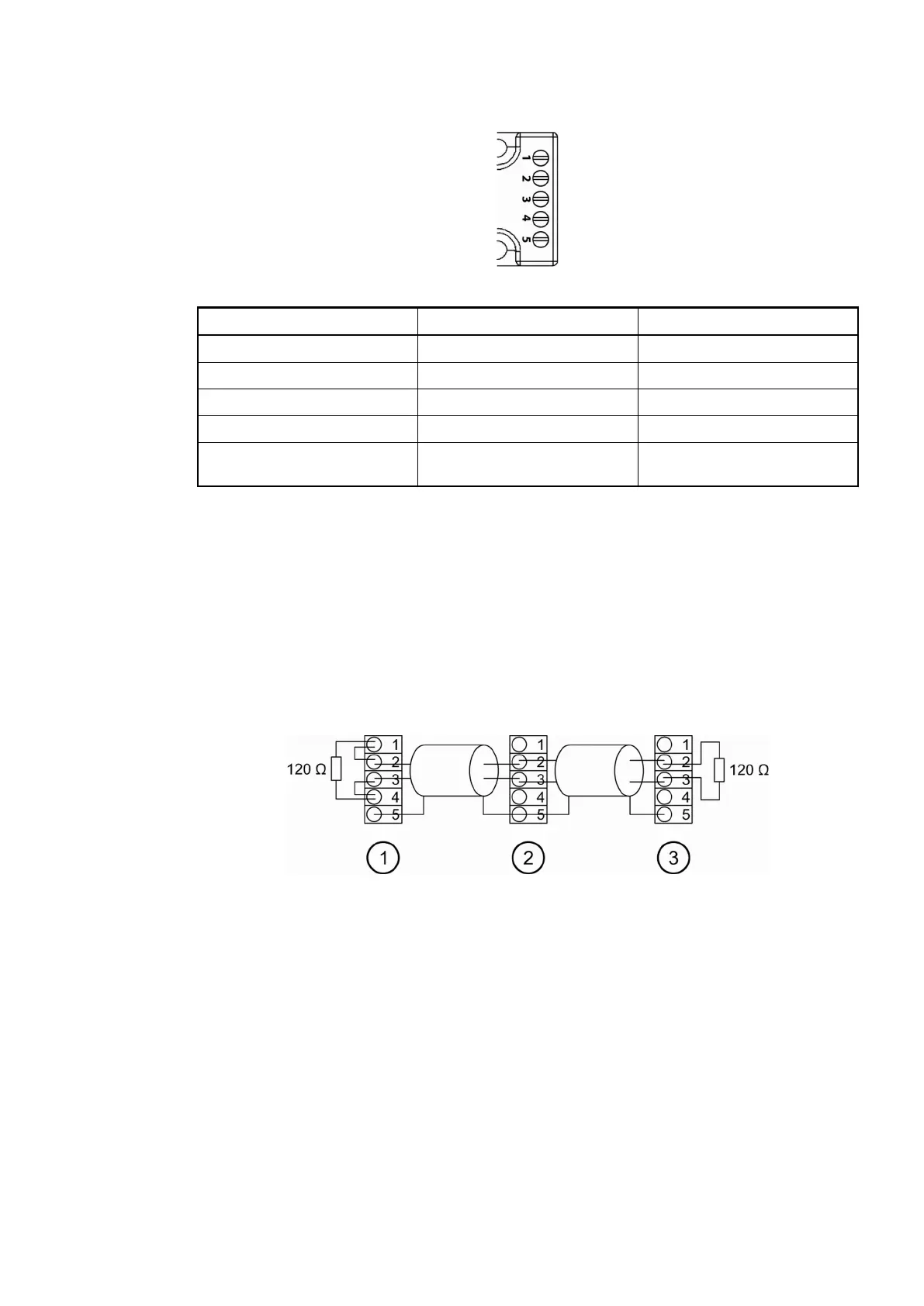
The following figure shows an RS-485 bus with the bus master at the line end.
1 Master at the bus line end, pull-up and pull-down activated, bus termination with 120 W
resistors
2 Slave within the bus line
3 Slave at the bus line end, bus termination with 120 W resistors
If the master is located within the bus line, it does not need a terminating resistor. The pull-up
and the pull-down resistors, however, are necessary:
Connection:
Interface
Connection:
Modbus Pro-
tocol
2019/04/173ADR010121, 13, en_US1142