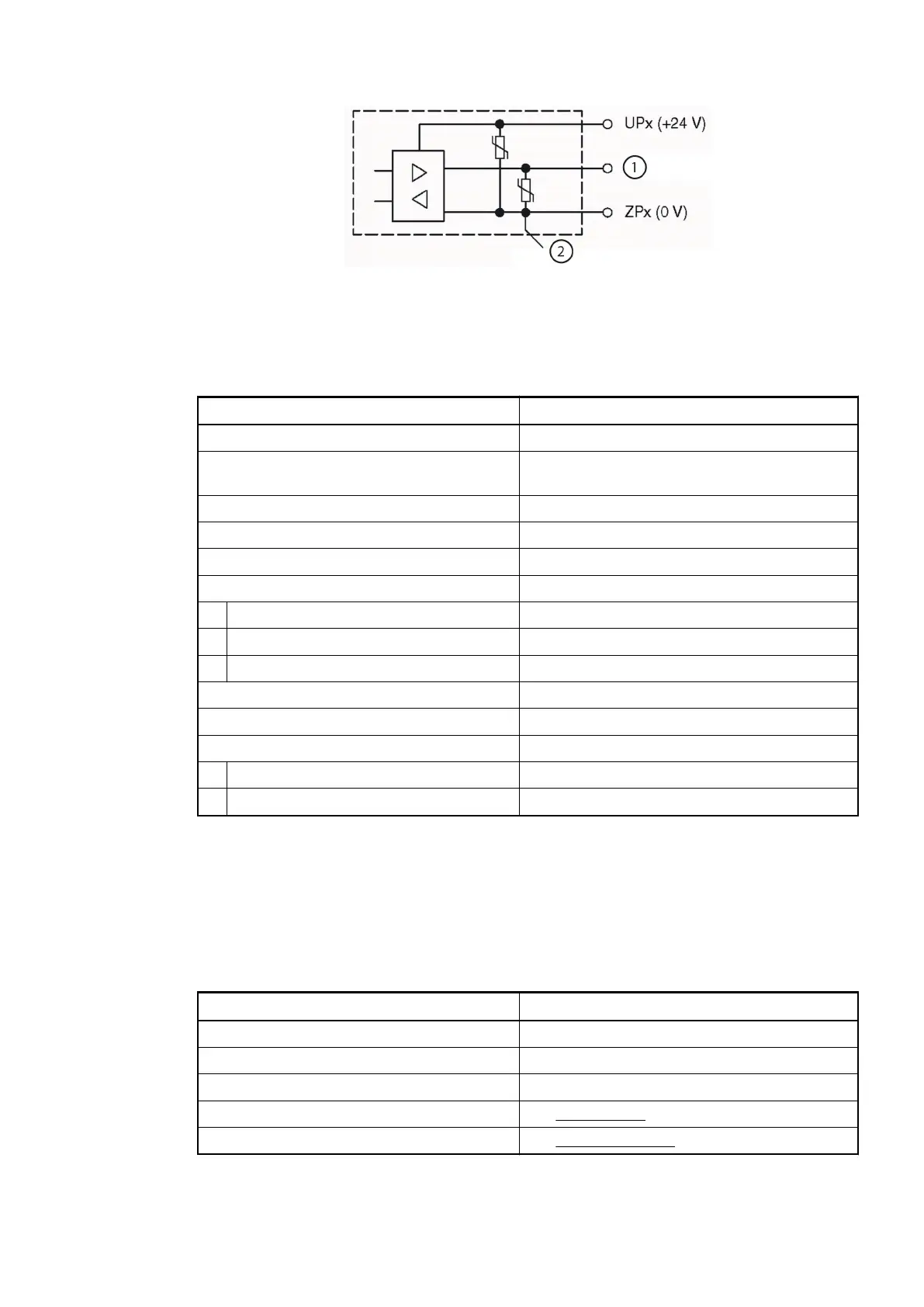
1 Digital input/output
2 For demagnitization when inductive loads are switched off
Technical Data of the Digital Inputs/Outputs if used as Inputs
Parameter Value
Number of channels per module Max. 16 digital inputs
Reference potential for all inputs Terminals 1.9...4.9 (minus pole of the process
supply voltage, signal name ZP)
Input current, per channel Technical Data of the Digital Inputs
Input type acc. to EN 61131-2 Type 1
Input delay (0->1 or 1->0) Typ. 8 ms, configurable from 0.1 to 32 ms
Input signal voltage 24 VDC
Signal 0 -3 V...+5 V *)
Undefined signal > +5 V...< +15 V
Signal 1 +15 V...+30 V
Ripple with signal 0 within -3 V...+5 V *)
Ripple with signal 1 within +15 V...+30 V
Max. cable length
Shielded 1000 m
Unshielded 600 m
*) Due to the direct connection to the output, the demagnetizing varistor is also effective at the
input (see figure) above. This is why the difference between UPx and the input signal may not
exceed the clamp voltage of the varistor. The varistor limits the voltage to approx. 36 V. Fol-
lowing this, the input voltage must range from -12 V to +30 V when UPx = 24 V and from
-6 V to +30 V when UPx = 30 V.
Technical Data of the Fast Counter
Parameter Value
Used inputs C16 / C17
Used outputs C18
Counting frequency Max. 50 kHz
Detailed description See Fast Counter
Operating modes See Operating modes
Communication Interface Modules (S500) > CS31
2019/04/173ADR010121, 13, en_US826