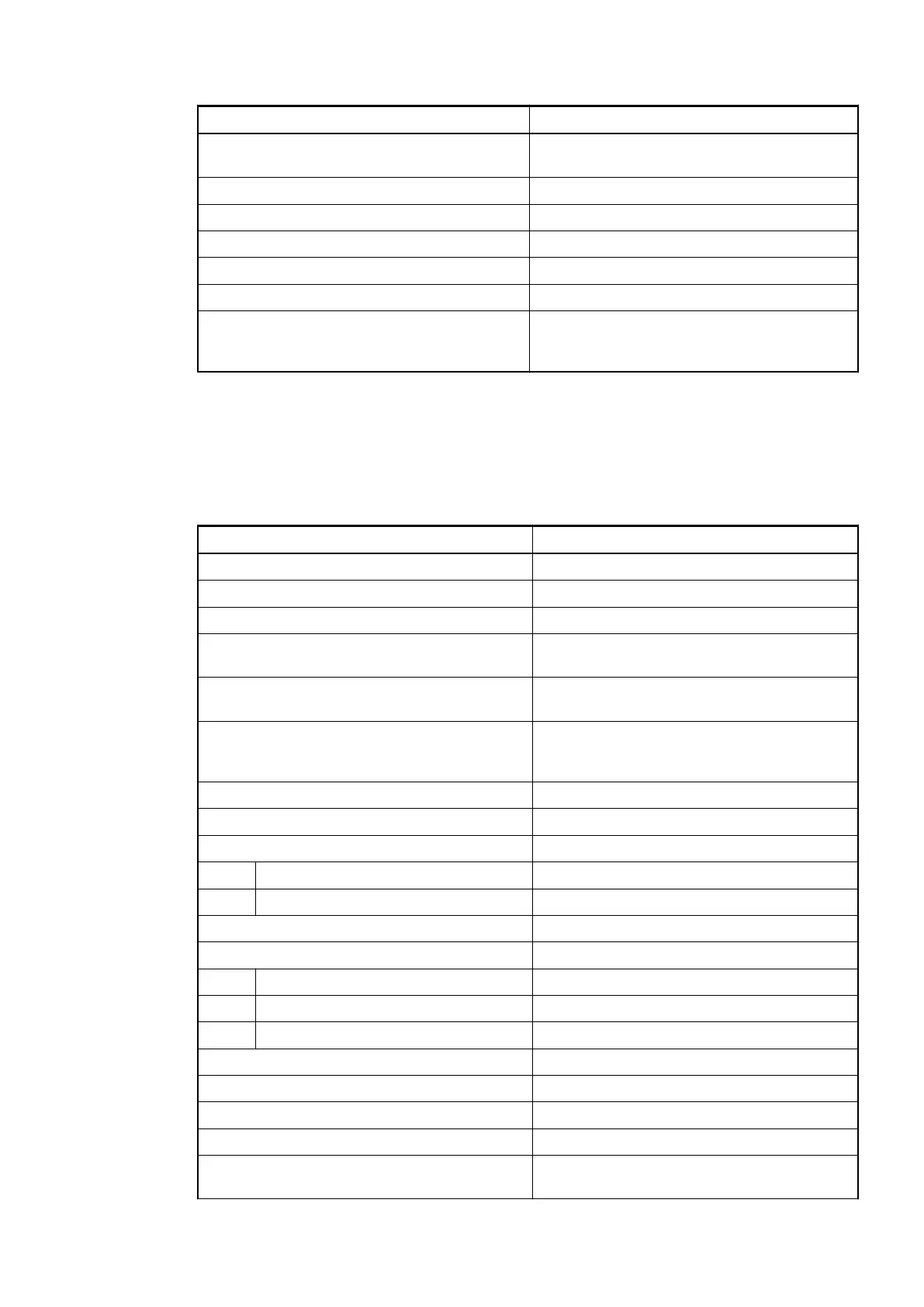
Parameter Value
Galvanic isolation Yes, between the output group and the rest of
the module
Isolated groups 1 (8 channels per group)
Surge-voltage (max.) 35 VDC for 0.5 s
Power dissipation within the module (max.) 1.6 W
Weight Ca. 115 g
Mounting position Horizontal or vertical
Cooling The natural convection cooling must not be
hindered by cable ducts or other parts in the
switch-gear cabinet.
No effects of multiple overloads on isolated multi-channel modules occur, as every channel is
protected individually by an external fuse.
Technical Data of the Digital Outputs
Parameter Value
Number of channels per module 8 transistor outputs (24 VDC, 0.5 A max.)
Distribution of the channels into groups 1 (8 channels per group)
Connection of the channels O0 to O7 Terminals 11 to 18
Common power supply voltage Terminal 19 (plus pole of the process voltage,
signal name UP)
Reference potential for the channels O0 to O7 Terminal 20 (minus pole of the process
voltage, signal name ZP)
Indication of the output signals 1 yellow LED per channel; the LED is on
when the output signal is high (signal 1) and
the module is powered via the I/O bus
Way of operation Non-latching type
Min. output voltage at signal 1 20 VDC at max. current consumption
Output delay (max. at rated load)
0 to 1 50 µs
1 to 0 200 µs
Output data length 1 byte
Output current
Rated current per channel (max.) 0.5 A at UP 24 VDC
Rated current per group (max.) 4 A
Lamp load (max.) 5 W
Max. leakage current with signal 0 0.5 mA
Output type Non-protected
Protection type External fuse on each channel
Rated protection fuse (for each channel) 3 A fast
Demagnetization when inductive loads are
switched off
Must be performed externally according to
driven load specification
No effects of
multiple over-
loads
I/O Modules > Digital I/O Modules
2019/04/17 3ADR010121, 13, en_US 229