Technical Data
The System Data of AC500-eCo apply
Ä
Chapter 2.5.1 “System Data AC500-eCo”
on page 1192
Only additional details are therefore documented below.
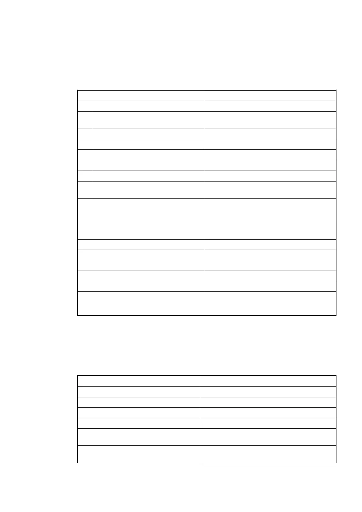
Parameter Value
Process supply voltage UP
Connections Terminal 19 for UP (+24 VDC) and terminal 20
for ZP (0 VDC)
Rated value 24 VDC
Current consumption via UP terminal 20 mA + max. 0.5 A per output
Max. ripple 5 %
Inrush current
0.000002 A
2
s
Protection against reversed voltage Yes
Rated protection fuse for UP Recommended; the outputs must be protected
by an 3 A fast fuse
Current consumption from 24 VDC power
supply at the L+/UP and M/ZP terminals of
the CPU/bus module
Ca. 10 mA
Galvanic isolation Yes, between the output group and the rest of
the module
Isolated groups 1 (16 channels per group)
Surge-voltage (max.) 35 VDC for 0.5 s
Max. power dissipation within the module 1.4 W
Weight Ca. 125 g
Mounting position Horizontal or vertical
Cooling The natural convection cooling must not be hin-
dered by cable ducts or other parts in the
switch-gear cabinet.
No effects of multiple overloads on isolated multi-channel modules occur, as every channel is
protected individually by an external fuse.
Technical Data of the Digital Outputs
Parameter Value
Number of channels per module 16 transistor outputs (24 VDC, 0.5 A max.)
Distribution of the channels into groups 1 (16 channels per group)
Connection of the channels O0 to O7 Terminals 1 to 9
Connection of the channels O8 to O15 Terminals 11 to 18
Common power supply voltage Terminal 19 (positive pole of the process voltage,
signal name UP)
Reference potential for the channels O0 to
O15
Terminal 20 (negative pole of the process
voltage, signal name ZP)
No effects of
multiple over-
loads
I/O Modules > Digital I/O Modules
2019/04/173ADR010121, 13, en_US238