The use of differential inputs helps to considerably increase the measuring accuracy and to
avoid earthing loops.
With differential input configurations, two adjacent analog channels belong together (e.g. the
channels 0 and 1). In this case, both channels are configured according to the desired operating
mode. The lower address must be the even address (channel 0), the next higher address must
be the odd address (channel 1). The converted analog value is available at the higher address
(channel 1).
The analog value is calculated by subtraction of the input value with the higher address from the
input value of the lower address.
The converted analog value is available at the odd channel (higher address).
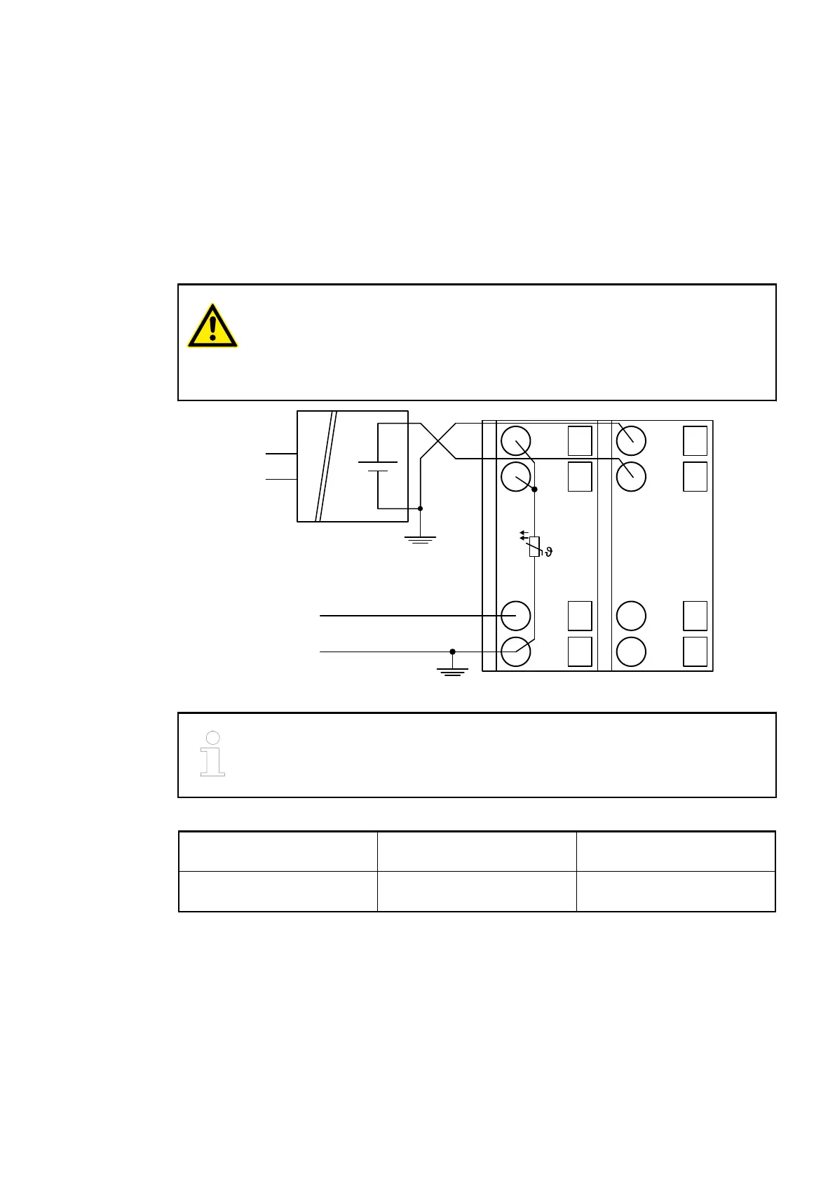
CAUTION!
The earthing potential at the sensors must not have too large a potential differ-
ence with respect to ZP (max. ±1 V within the full signal range). Otherwise,
problems may occur concerning the common-mode input voltages of the
involved analog inputs.
UP
ZP
1.0
I0-
1.1
I1-
1.8
UP
1.9
ZP
PTC
2.0
I0+
2.1
I1+
2.8
UP
2.9
ZP
0 ... 10 V
-10 ... +10 V
+
-
U
IN
Fig. 76: Connection example
The negative pole of the sensor must be earthed next to the sensor.
Voltage 0 V...10 V with differential inputs, 2 chan-
nels used
Voltage -10 V...+10 V with differential inputs, 2 chan-
nels used
In order to avoid error messages or long processing times, it is useful to configure unused
analog input channels as "unused".
Use of Analog Inputs as Digital Inputs
Several (or all) analog inputs can be configured as digital inputs. The inputs are not electrically
isolated against the other analog channels.
I/O Modules > Analog I/O Modules
2019/04/17 3ADR010121, 13, en_US 553