If the bus module is configured as a Fast Counter module and '0 - no Counter'
in Automation Builder is selected the channel ERR LEDs stays on and the
module does not start up. The address was adjusted with '71'.
Only the '0- no Counter' mode does not operate. If any other counter is selected
e.g. '1-1 Up counter' the module starts up and can be utilized.
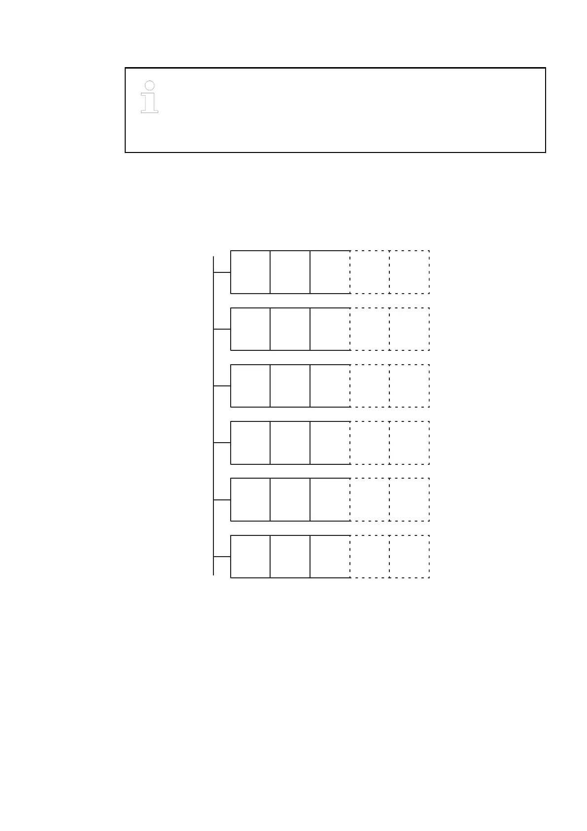
Small Overview of the Addressing Possibilities
Configuration example with 32 analog inputs with or without 32 analog outputs (Fast Counter
not used) = 5 bus addresses by the bus module
DC551
8 DI
16 DC
16 AI 16 AI 16 AO 16 AOn
DC551
8 DI
16 DC
16 AI 16 AI 16 AO 16 AOmini n+2
DC551
8 DI
16 DC
16 AI 16 AI 16 AO 16 AO
DC551
8 DI
16 DC
16 AI 16 AI 16 AO 16 AO
DC551
8 DI
16 DC
16 AI 16 AI 16 AO 16 AO
DC551
8 DI
16 DC
16 AI 16 AI 16 AO 16 AO
Switch
mini n+4
mini n+6
mini n+8
mini n+10
address
If the number of analog outputs is less than the number of analog inputs, no additional address
is necessary. Change the type from "analog in" to "analog I/O".
● 30 bus addresses used, 1 bus address free
● 192 analog inputs (+ 192 analog outputs)
● 48DI / 96DC (144 DI / 96 DO for CS31 and user program)
● Switch address incremented to avoid control overlap.
In CPU table module switch address n will be seen as (idem for AC500 or old CPU):
● Address n, type digital I/O, 8 DI/16 DC
● Address n, type analog I or I/O, 8 AI (+ 8 AO)
● Address n + bit 8/15=1, type analog I or I/O, 8 AI (+ 8 AO)
● Address n+1, type analog I or I/O, 8 AI (+ 8 AO)
● Address n+1 + bit 8/15=1, type analog I or I/O, 8 AI (+ 8 AO)
Communication Interface Modules (S500) > CS31
2019/04/17 3ADR010121, 13, en_US 817