1.7.2.1.2 Functionality
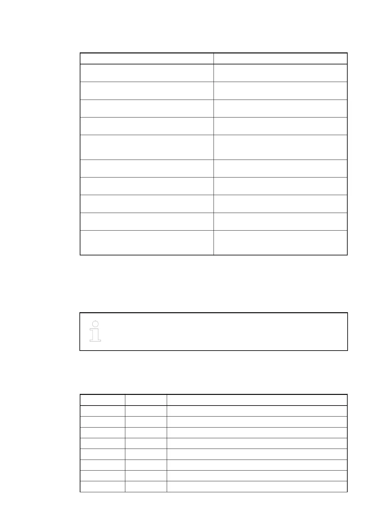
Parameter Value
Interface bus A RS485, CS31 protocol, electrically isolated
from other electronic.
Interface bus B RS485, CS31 protocol, electrically isolated
from other electronic.
Address switches Two rotary switches for setting the CS31 bus
address (00d to 99d).
I/O bus I/O bus to connect S500 I/O modules (max.
7).
Digital inputs/outputs 16 configurable digital inputs/outputs in one
group: 24 VDC, 0.5 A (max.), short-circuit and
overload protected.
High-Speed Counter Integrated, with many configurable operating
modes.
LED displays For system states, signal states, errors and
power supply.
External power supply Via UP and ZP terminal (process voltage: 24
VDC).
Effect of incorrect input terminal connection Wrong or no signal detected, no damage up to
35 V
Required terminal unit
TU552-CS31
Ä
Chapter 1.4.7 “TU551-CS31
and TU552-CS31 for CS31 Communication
Interface Modules” on page 168
1.7.2.1.3 Electrical Connection
The CS31-HA bus module CI590-CS31-HA is plugged on CS31 terminal unit TU551-CS31 or
TU552-CS31. Hereby, it clicks in with two mechanical locks. The terminal unit is mounted on a
DIN rail or with two screws plus the additional accessory for wall mounting (TA526).
Mounting, disassembling and electrical connection for the terminal units and the
I/O modules are described in detail in the S500 system data chapters.
The electrical connection is carried out by using the 40 terminals of the terminal unit TU551-
CS31/TU552-CS31. It is possible to replace the CI590-CS31-HA without loosening the wiring.
Assignment of the terminals:
Terminal Signal Description
1.0 R1A Integrated termination resistors for CS31 bus A, terminal 1
1.1 R2A Integrated termination resistors for CS31 bus A, terminal 2
1.2 B1A CS31 bus A, bus line 1
1.3 B2A CS31 bus A, bus line 2
1.4 FE Functional earth
1.5 B1A CS31 bus A, bus line 1
1.6 B2A CS31 bus A, bus line 2
1.7 FE Functional earth
Communication Interface Modules (S500) > CS31
2019/04/17 3ADR010121, 13, en_US 761