According to IEC 60204-1:2016, where control circuits are supplied from an AC
source, transformers having separate windings shall be used to separate the
power supply from the control supply.
2.5.4.2 Serial Interface COM1
The serial interfaces COM1 and COM2 are designed according to the standard EIA RS-485.
Both interfaces can be operated in RS-485 mode.
Parameter Value
Standard of the serial interfaces RS-485
Interface connectors COM1: 9-pin D-sub connector (female)
COM2: 5-pole connector with screw-type con-
nection (optional)
Electrical isolation none
Serial interface parameters Configurable by the software
Operating modes Programming or data exchange
Supported protocols Modbus or serial data exchange using special
software function blocks
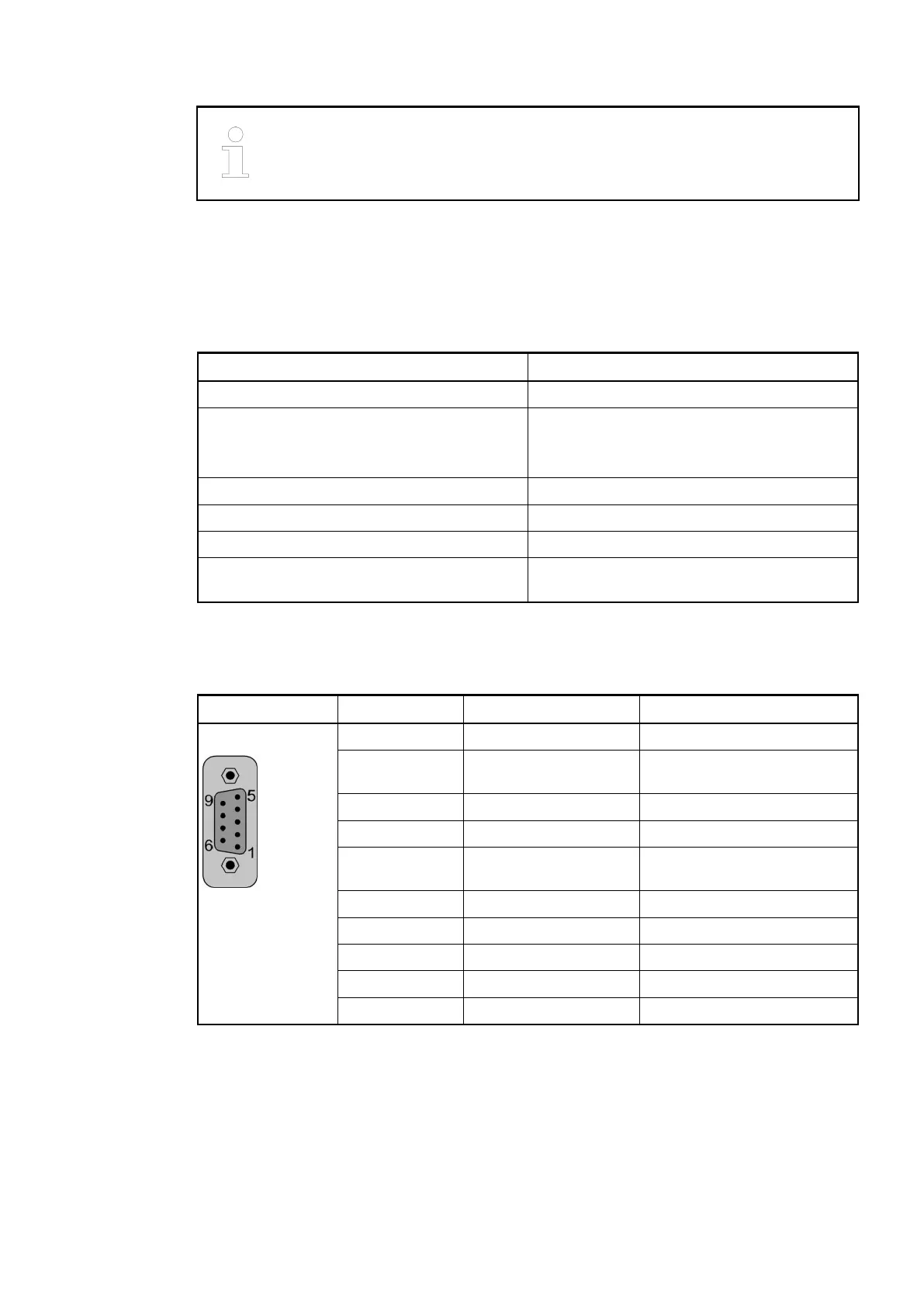
Table 208: Pin assignment
Serial Interface Pin Signal Description
Serial Interface 1 FE Functional earth
2 SGND 0 V power supply, internally
connected to M terminal
3 RxD/TxD-P Receive/Transmit positive
4 Reserved Reserved, not connected
5 SGND 0 V power supply, internally
connected to M terminal
6 +3.3 V 3.3 V power supply
7 Reserved Reserved, not connected
8 RxD/TxD-N Receive/Transmit negative
9 Reserved Reserved, not connected
Shield Cable shield Functional earth
The serial non-isolated interface COM1 is connected to a 9-pole D-sub connector. It is configu-
rable for RS-485 and can be used for:
● online access with Automation Builder (via RS-485 programming cable e. g. TK504
Ä
Chapter 1.8.1.9 “TK504 - Programming Cable” on page 1127),
● as Modbus RTU, client and server
● for ASCII serial protocols
● a CS31 system bus (RS-485), as master only.
System Assembly, Construction and Connection
AC500-eCo > Connection and Wiring
2019/04/173ADR010121, 13, en_US1210