Voltage 0...10 V 1 channel used
Voltage -10 V...+10 V 1 channel used
The measuring ranges are described in the section Measuring Ranges
Ä
Chapter 1.7.3.1.7
“Parameterization” on page 842
Ä
Chapter 1.7.3.1.10 “Measuring Ranges” on page 851.
In order to avoid error messages or long processing times, it is useful to configure unused
analog input channels as "unused".
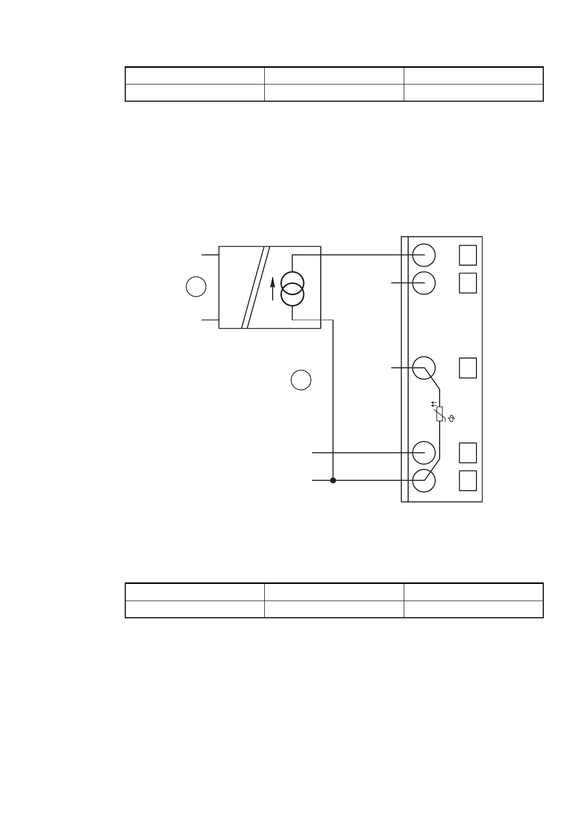
Connection of Active-type Analog Sensors (Current) with Electrically Isolated Power Supply
The following figure shows the connection of active-type analog sensors (current) with electri-
cally isolated power supply.
1.0
1.1
1.8
1.9
AI0+
AI1+
UP
ZP
UP
ZP
PTC
1.5
AI–
1
2
+
–
0...20 mA
4...20 mA
Fig. 163: Connection of active-type analog sensors (current) with electrically isolated power
supply
1 1 analog sensor requires 1 channel
2 Electrically isolated power supply for the analog sensor
Current 0...20 mA 1 channel used
Current 4...20 mA 1 channel used
The measuring ranges are described in the section Measuring Ranges
Ä
Chapter 1.7.3.1.7
“Parameterization” on page 842
Ä
Chapter 1.7.3.1.10 “Measuring Ranges” on page 851.
Unused input channels can be left open-circuited, because they are of low resistance.
Connection of Active-type Analog Sensors (Voltage) with no Electrically Isolated Power Supply
The following figure shows the connection of active-type sensors (voltage) with no electrically
isolated power supply.
Communication Interface Modules (S500) > EtherCAT
2019/04/17 3ADR010121, 13, en_US 835