EasyManuals Logo

ABB AC500 PLC User Manual

ABB AC500 PLC
1315 pages
To Next Page IconTo Next Page
To Previous Page IconTo Previous Page
Page #791 background imageLoading...
Page #791 background image
Fig. 154: Use of analog inputs as digital inputs
Digital input 24 V 1 channel used
The measuring ranges are described in the section Measuring Ranges
Ä
Chapter 1.7.2.2.8
“Parameterization” on page 794
Ä
Chapter 1.7.2.2.11 “Measuring Ranges” on page 802:
Connection of Analog Output Loads (Voltage)
The following figure shows the connection of output loads to the analog output AO0. Proceed
with the analog output AO1 in the same way.
Fig. 155: Connection of analog output loads (voltage)
Device Specifications
Communication Interface Modules (S500) > CS31
2019/04/17 3ADR010121, 13, en_US 791
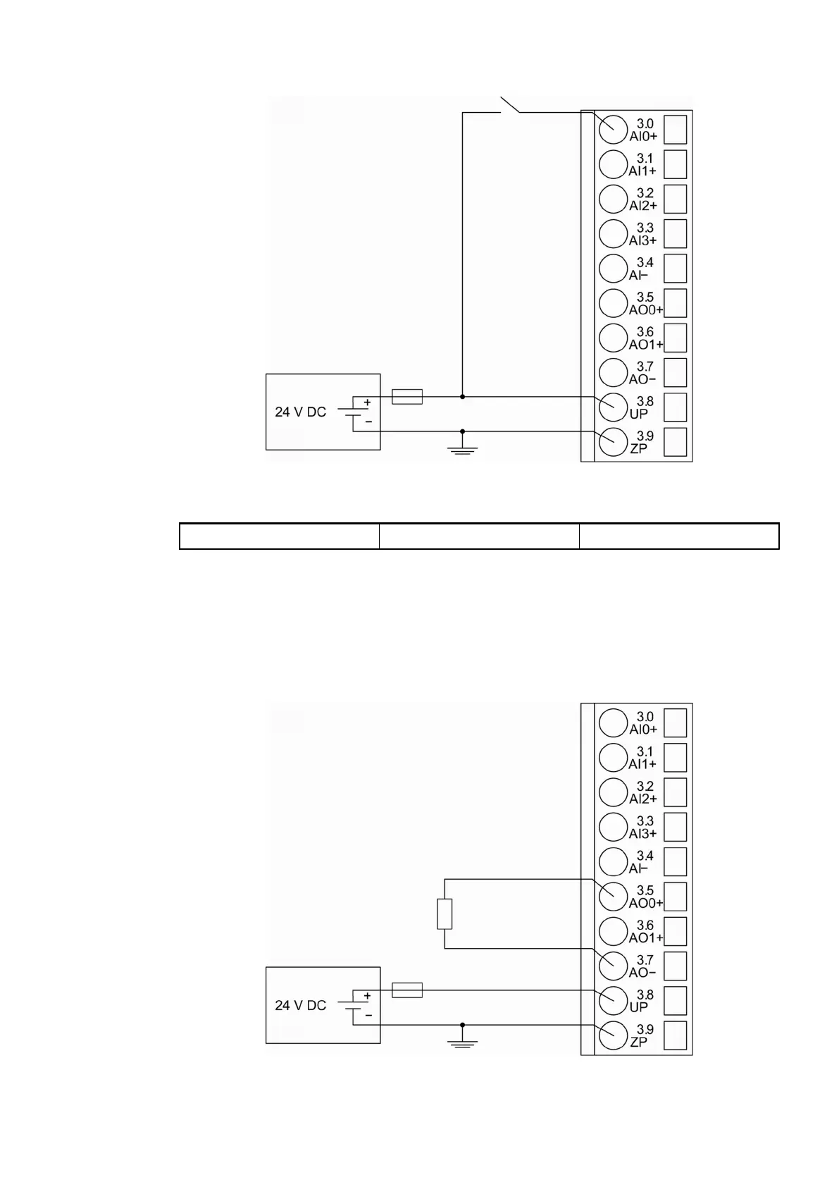
Table of Contents

Questions and Answers:

Question and Answer IconNeed help?

Do you have a question about the ABB AC500 PLC and is the answer not in the manual?

ABB AC500 PLC Specifications

General IconGeneral
Digital InputsUp to 1024
Digital OutputsUp to 1024
Real-time clockYes
Power Supply24 V DC
Protection ClassIP20
ProcessorARM based
Programming LanguagesIEC 61131-3 (LD, ST, FBD, SFC, IL)
Operating Temperature-25°C to +70°C
Communication InterfacesEthernet, CAN, RS-232, RS-485

Related product manuals