The I/O module must not be used as a decentralized I/O module with CI590-
CS31-HA bus modules.
Functionality
Parameter Value
LED displays For signal states
Internal power supply Via I/O bus
External power supply Not necessary
Electrical Connection
For a detailed description of the mounting, disassembly and electrical connec-
tion of the module, please refer to the System Assembly chapter
Ä
Chapter 2.5
“AC500-eCo” on page 1192.
The electrical connection is carried out by using a removable 9-pin terminal block. These ter-
minal blocks differ in their connection system (spring terminals or screw terminals, cable
mounting from the front or from the side). For more information, please refer to the chapter ter-
minal blocks for S500-eCo I/O modules
Ä
Chapter 1.8.3.2 “TA563-TA565 - Terminal Blocks”
on page 1164. The terminal blocks are not included in the module's scope of delivery and must
be ordered separately.
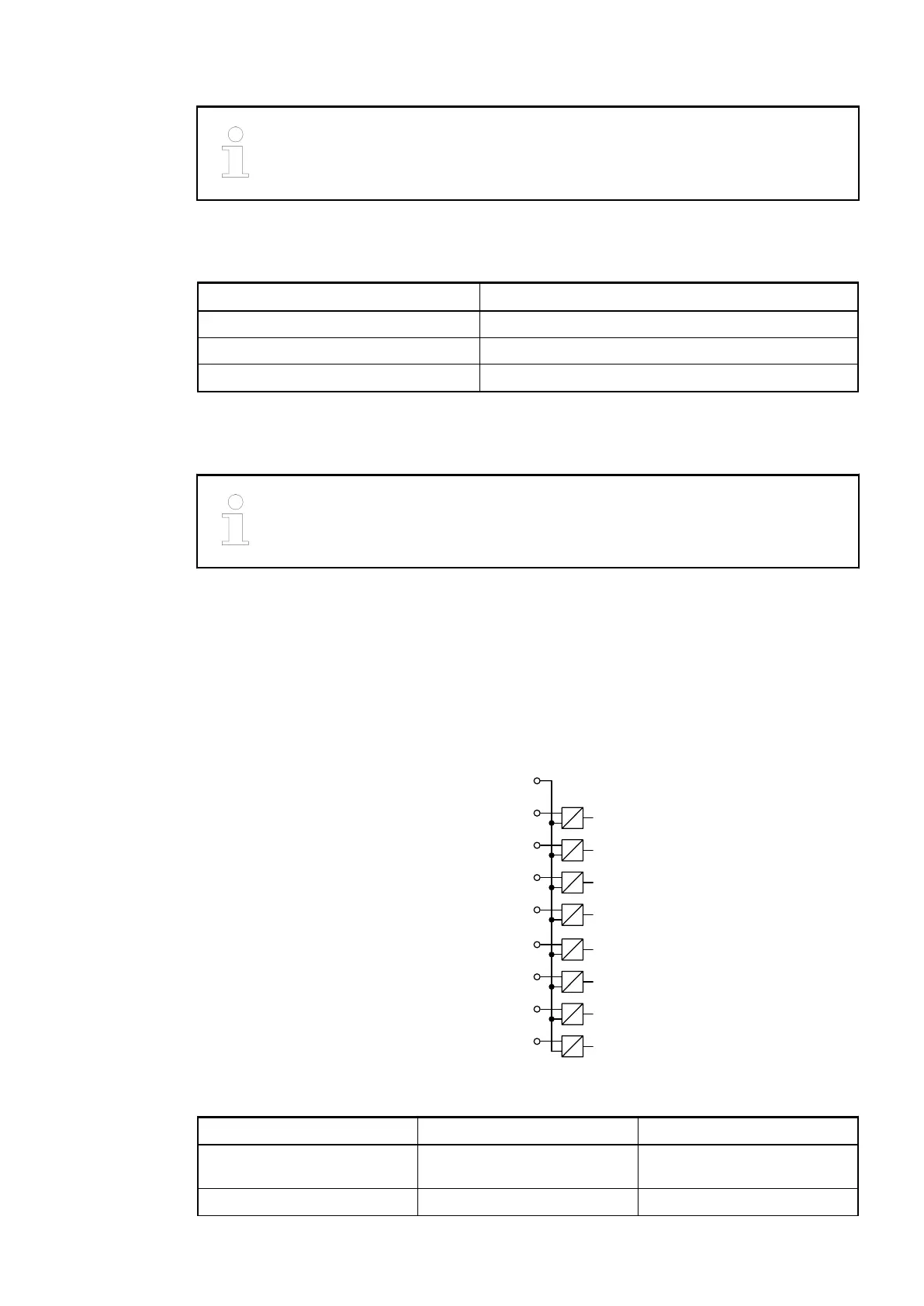
The following block diagram shows the internal construction of the digital inputs:
I0 2
I1 3
I2 4
I3 5
I4 6
I5 7
I6 8
I7 9
C0..7 1
Table 40: Assignment of the Terminals:
Terminal Signal Description
1 C0...7 Input common for signals I0 to
I7
2 I0 Input signal I0
I/O Modules > Digital I/O Modules
2019/04/17 3ADR010121, 13, en_US 191