CAUTION!
Risk of faulty measurements!
The minus pole at the sensors must not have a too big potential difference with
respect to ZP (max. ±1 V).
Make sure that the potential difference never exceeds ±1 V (also not with long
cable lengths).
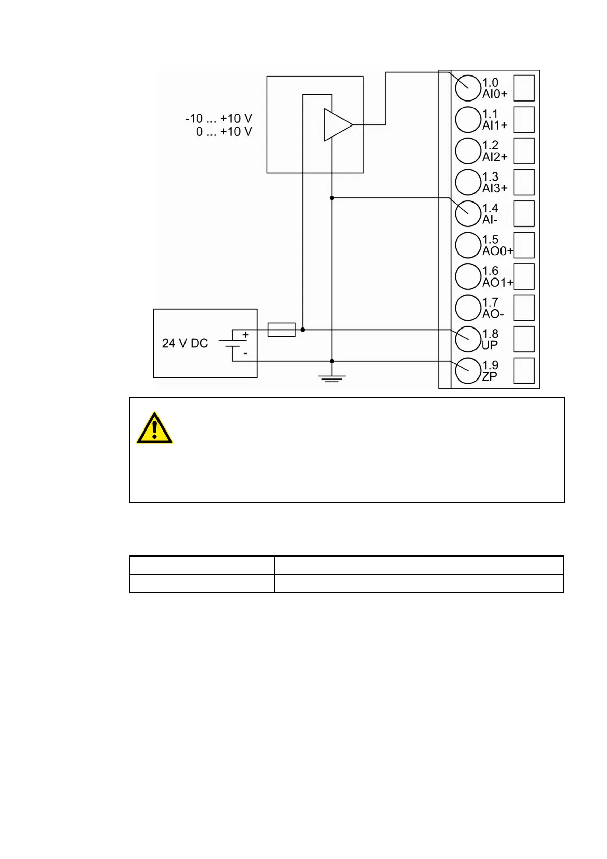
The following measuring ranges can be configured
Ä
Chapter 1.7.6.2.7 “Parameterization”
on page 1024
Ä
Chapter 1.7.6.2.7 “Parameterization” on page 1024:
Voltage 0 V...10 V 1 channel used
Voltage -10 V...+10 V 1 channel used
The function of the LEDs is described under Diagnosis and displays / Displays
Ä
Chapter
1.7.6.2.8 “Diagnosis and State LEDs” on page 1030.
To avoid error messages from unused analog input channels, configure them as "unused".
Connection of Passive-type Analog Sensors (Current) to the Analog Inputs
The following figure shows the connection of passive-type analog sensors (current) to the
analog input AI0. Proceed with the analog inputs AI1 to AI3 in the same way.
Communication Interface Modules (S500) > PROFINET
2019/04/173ADR010121, 13, en_US1018