Functionality
2 analog RTD-inputs, individually configurable for
● Not used (default)
● Pt100, -50 °C...+400 °C, 2-wire
● Pt100, -50 °C...+400 °C, 3-wire
● Pt1000, -50 °C...+400 °C, 2-wire
● Pt1000, -50 °C...+400 °C, 3-wire
● Ni1000, -50 °C...+150 °C, 2-wire
● Ni1000, -50 °C...+150 °C, 3-wire
● Ni100, -50 °C...+150 °C, 2-wire
● Ni100, -50 °C...+150 °C, 3-wire
● Analog input resistance 0 W...150 W
● Analog input resistance 0 W...300 W
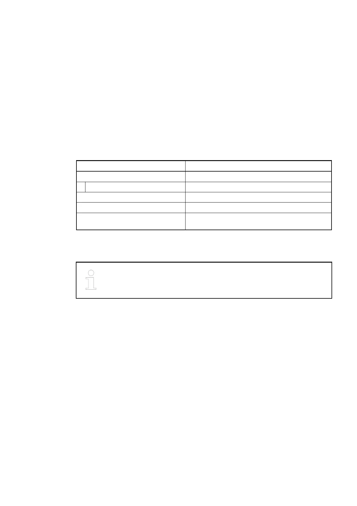
Parameter Value
Resolution of the analog channels
Temperature 0.1 °C
LED displays 2 LEDs for process voltage and error messages
Internal supply Via I/O bus
External supply Via the terminals UP (process voltage 24 VDC) and
ZP (0 VDC)
Electrical Connection
For a detailed description of the mounting, disassembly and electrical connec-
tion of the module, please refer to the System Assembly chapter
Ä
Chapter 2.5
“AC500-eCo” on page 1192.
The electrical connection is carried out by using a removable 11-pin terminal block. These ter-
minal blocks differ in their connection system (spring terminals or screw terminals, cable
mounting from the front or from the side).
Ä
Chapter 1.8.3.2 “TA563-TA565 - Terminal Blocks”
on page 1164. The terminal blocks are not included in the module's scope of delivery and must
be ordered separately.
The following block diagram shows the internal construction of the analog inputs:
I/O Modules > Analog I/O Modules
2019/04/17 3ADR010121, 13, en_US 407