1.4.7.1 Technical Data
The System Data of AC500 and S500
Ä
Chapter 2.6.1 “System Data AC500” on page 1248 are
valid for standard version.
The System Data of AC500-XC
Ä
Chapter 2.7.1 “System Data AC500-XC” on page 1309 are
valid for the XC version.
Only additional details are therefore documented below.
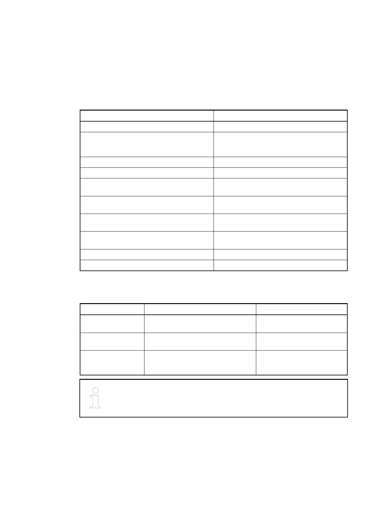
Parameter Value
Number of channels per module 24
Distribution of the channels into groups 3 groups of 8 channels each (2.0...2.7,
3.0...3.7, 4.0...4.7), the allocation of the chan-
nels is given by the inserted CS31 bus module
CS31 field bus connector Terminals 1.0 to 1.7
Rated voltage 24 VDC
Max. permitted total current 10 A (between the terminals 1.8...4.8 and
1.9...4.9)
Earthing Direct connection to the earthed DIN rail or via
the screws with wall mounting
Screw terminals Front terminal, conductor connection vertically
with respect to the printed circuit board
Spring terminals Front terminal, conductor connection vertically
with respect to the printed circuit board
Weight 200 g
Mounting position Horizontal or vertical
1.4.7.2 Ordering Data
Part No. Description Product Life Cycle Phase *)
1SAP 210 600
R0001
TU551-CS31, CS31 bus terminal unit,
24 VDC, screw terminals
Active
1SAP 210 400
R0001
TU552-CS31, CS31 bus terminal unit,
24 VDC, spring terminals
Active
1SAP 410 400
R0001
TU552-CS31-XC, CS31 bus terminal
unit, 24 VDC, spring terminals,
XC version
Active
*) For planning and commissioning of new installations use modules in Active
status only.
Terminal Units (AC500 Standard) > TU551-CS31 and TU552-CS31 for CS31 Communication Interface Modules
2019/04/173ADR010121, 13, en_US170