If using TU517/TU518, note that the termination resistors are not located inside
the TU, but inside the bus module CI541-DP. I. e. when removing the device
from the TU, the bus termination resistors are not connected to the bus any
more. The bus itself will not be disconnected if a device is removed.
If using TU517/TU518 the max. permitted baud rate is limited to 1.5 MBaud.
The earthing of the shield should take place at the switch-gear cabinet, see
System Data AC500
Ä
Chapter 2.6.1 “System Data AC500” on page 1248.
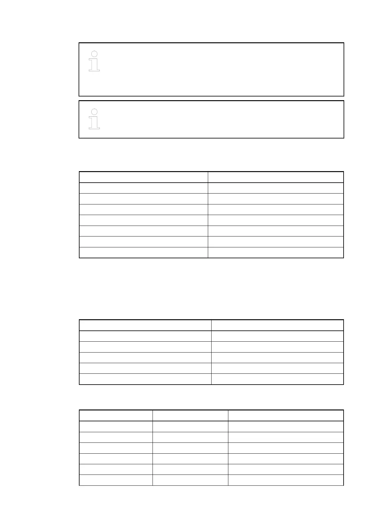
Technical Data Bus Cable
Parameter Value
Type Twisted pair (shielded)
Characteristic impedance 135...165 W
Cable capacity < 30 pF/m
Conductor diameter of the cores ³ 0.64 mm
Conductor cross section of the cores ³ 0.34 mm²
Cable resistance per core £ 55 W/km
Loop resistance (resistance of two cores) £ 110 W/km
Cable Length
The maximum possible cable length of a PROFIBUS subnet within a segment depends on the
baud rate (transmission rate).
Baud rate Maximum cable length
9.6 kBaud to 93.75 kBaud 1200 m
187.5 kBaud 1000 m
500 kBaud 400 m
1.5 MBaud 200 m
3 MBaud to 12 MBaud 100 m
The assignment of the other terminals:
Terminal Signal Description
2.0 AI0+ Plus pole of analog input signal 0
2.1 AI1+ Plus pole of analog input signal 1
2.2 AI2+ Plus pole of analog input signal 2
2.3 AI3+ Plus pole of analog input signal 3
2.4 AI- Minus pole of analog input signals 0 to 3
2.5 AO0+ Plus pole of analog output signal 0
Communication Interface Modules (S500) > PROFIBUS
2019/04/17 3ADR010121, 13, en_US 947