1.6.2.2.5 Measuring Ranges
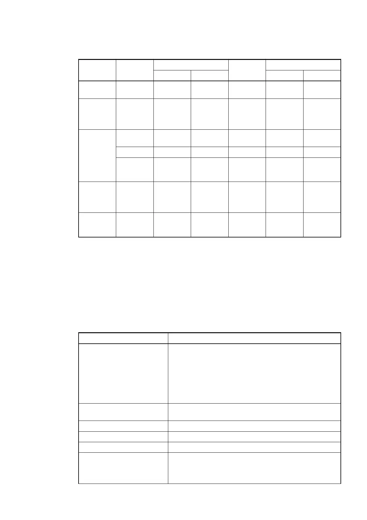
Table 99: Voltage input ranges
Range IEPE Digital value -10 V...+10
V
Digital value
Decimal Hex. Decimal Hex.
Open loop
overflow
≥ 7.5 3145728 300000 ≥ 12.0000 5033164 4CCCCC
Measured
value too
high
7.49999761
6...
6.00000238
3145727...
2516583
2FFFFF...
266667
11.9999976
2...
10.0000023
8
5033163...
4194305
4CCCCB...
400001
Normal
range
6.00000...
0.00000238
2516582...
1
266666... 1 10.0000...
0,00000238
4194304...
1
400000... 1
0.0000 0 0 0.0000 0 0
-0.0000023
8...
-6.00000
-1...
-2516582
-1...
-266666
-0.0000023
8...
-10.0000
-1...
-4194304
-1...
-400000
Measured
value too
low
-6.0000023
8...
-7.4999976
16
-2516583...
-3145727
-266667...
-2FFFFF
-10.000002
38...
-11.999997
62
-4194305...
-5033163
-400001...
-4CCCCB
Short cir-
cuit / under-
flow
≤ -7.5 -3145728 -300000 ≤ -12.0000 -5033164 -4CCCCC
1.6.2.2.6 Technical Data
The System Data of AC500 and S500
Ä
Chapter 2.6.1 “System Data AC500” on page 1248 are
valid for standard version.
The System Data of AC500-XC
Ä
Chapter 2.7.1 “System Data AC500-XC” on page 1309 are
valid for the XC version.
Only additional details are therefore documented below.
Table 100: Technical Data of Process Supply Voltage
Parameter Value
Connections of terminals The terminals 1.8, 4.8...7.8, 1.9, 4.9...7.9, 4.0...4.7, 7.0...7.7
are electrically interconnected within the TF5x1-CMS.
Terminals 1.8, 4.8...7.8: process voltage L+ = +24 VDC
Terminals 1.9, 4.9...7.9: process voltage M = 0 V
Terminals 4.0...4.7, 7.0...7.7: analog shield clamps SH
Terminal 1.0: FE shield clamp of encoder
Protection against reverse
voltage
Yes
Rated protection fuse at UP 10 A fast
Rated value 24 VDC
Max. ripple 5 %
Current consumption from L+
(FM502-CMS and PM592-
ETH, no communication
module)
Max. 0.43 A + max. 0.5 A per output
2019/04/17 3ADR010121, 13, en_US 691