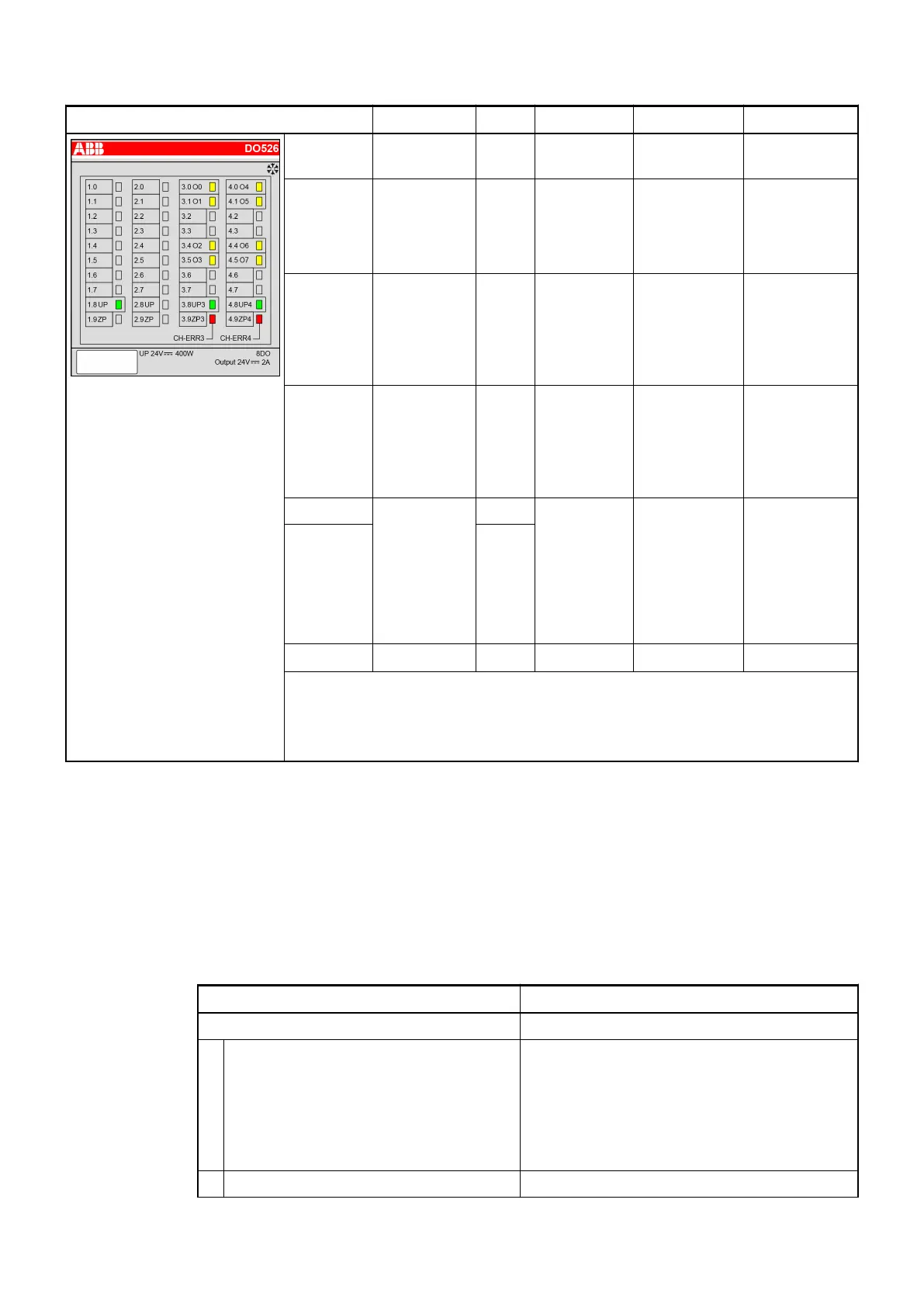
LED State Color LED = OFF LED = ON LED flashes
Outputs
O0...O7
Digital output Yellow Output =
OFF
Output = ON
2
)
--
UP Process
supply
voltage
24 VDC via
terminal
Green Process
supply
voltage is
missing
Process
supply voltage
OK
--
UP3 Process
supply
voltage out-
puts 0...3
24 VDC via
terminal
Green Process
supply
voltage is
missing
Process
supply voltage
OK
--
UP4 Process
supply
voltage out-
puts 4...7
24 VDC via
terminal
Green Process
supply
voltage is
missing
Process
supply voltage
OK
--
CH-ERR3 Channel
Error, error
messages in
groups (dig-
ital outputs
combined
into the
groups 3, 4)
Red No error or
process
supply
voltage is
missing
Severe error
within the cor-
responding
group
Error on in the
corresponding
group
CH-ERR4 Red
CH-ERR
1
)
Module Error Red -- Internal error --
1
) All of the LEDs CH-ERR3 to CH-ERR4 light up together
2
) The state of the LEDs corresponds to the logic state of the output. In case of
missing or low process supply voltage UP3 or UP4, the signal on the output ter-
minal is off even though the LED is on.
Technical Data
The System Data of AC500 and S500
Ä
Chapter 2.6.1 “System Data AC500” on page 1248 are
valid for standard version.
The System Data of AC500-XC
Ä
Chapter 2.7.1 “System Data AC500-XC” on page 1309 are
valid for the XC version.
Only additional details are therefore documented below.
Parameter Value
Process supply voltage UP, UP3 and UP4
Connections Terminals 1.8 and 2.8 for +24 V (UP) as well as
1.9 and 2.9 0 V (ZP)
Terminals 3.8 for +24 V (UP3) as well as 3.9 for
0 V (ZP3)
Terminals 4.8 for +24 V (UP4) as well as 4.9 for
0 V (ZP4)
Rated value 24 VDC
I/O Modules > Digital I/O Modules
2019/04/17 3ADR010121, 13, en_US 369