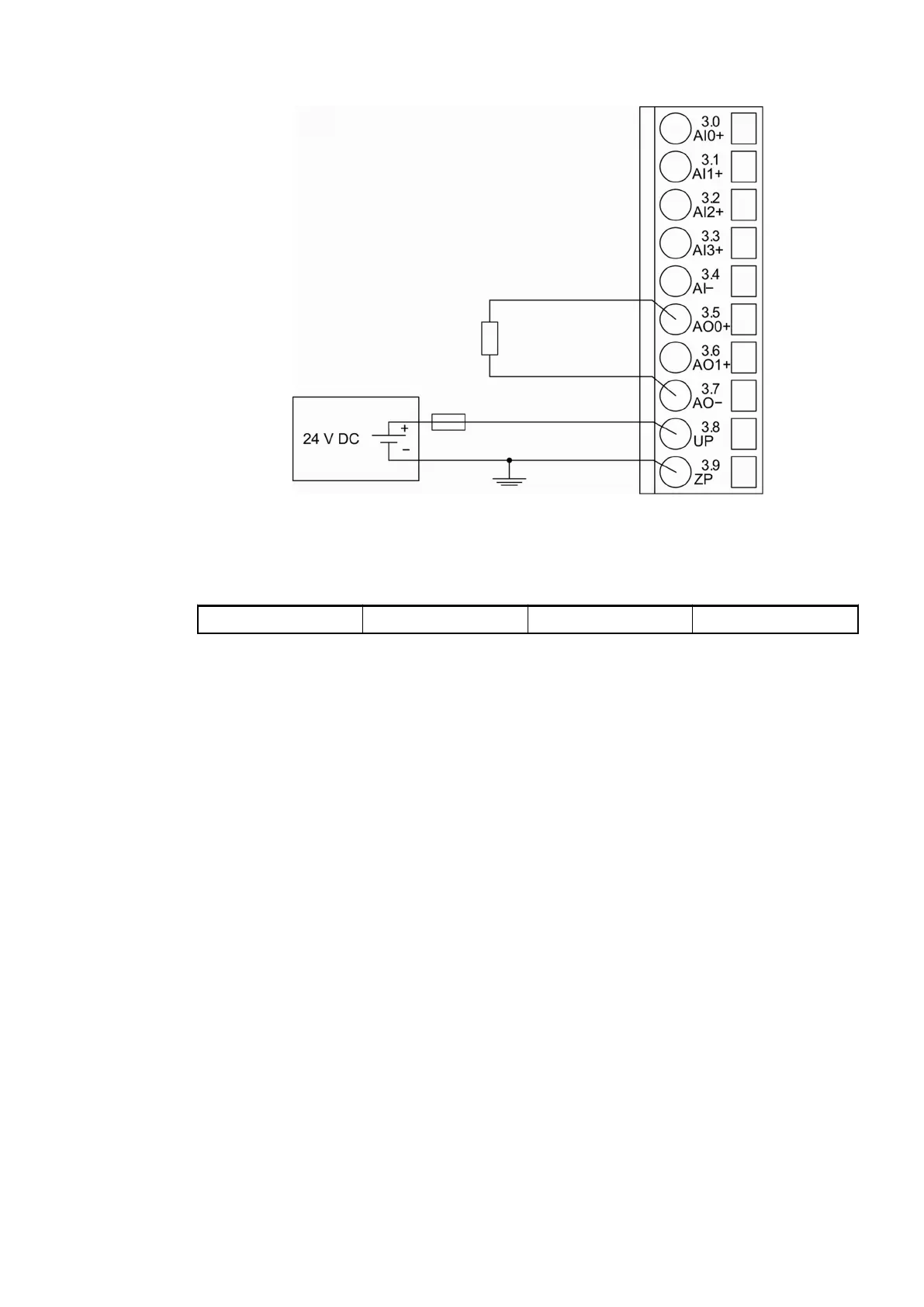
Fig. 90: Connection of analog output loads (voltage)
The following measuring ranges can be configured
Ä
Chapter 1.5.3.1.1.6 “Parameterization”
on page 585 :
Voltage -10 V...+10 V Load ±10 mA max. 1 channel used
For a description of the function of the LEDs, please refer to the Diagnosis and displays / Dis-
plays chapter
Ä
Chapter 1.5.3.1.1.8 “State LEDs” on page 592.
Unused analog outputs can be left open-circuited.
Connection of Analog Output Loads (Current)
The following figure shows the connection of output loads to the analog output AO0. Proceed
with the analog output AO1 in the same way.
I/O Modules > Digital/Analog I/O Modules
2019/04/17 3ADR010121, 13, en_US 583