Multiple overloads
No effects of multiple overloads on isolated multi-channel modules occur, as
every channel is protected individually by an internal smart high-side switch.
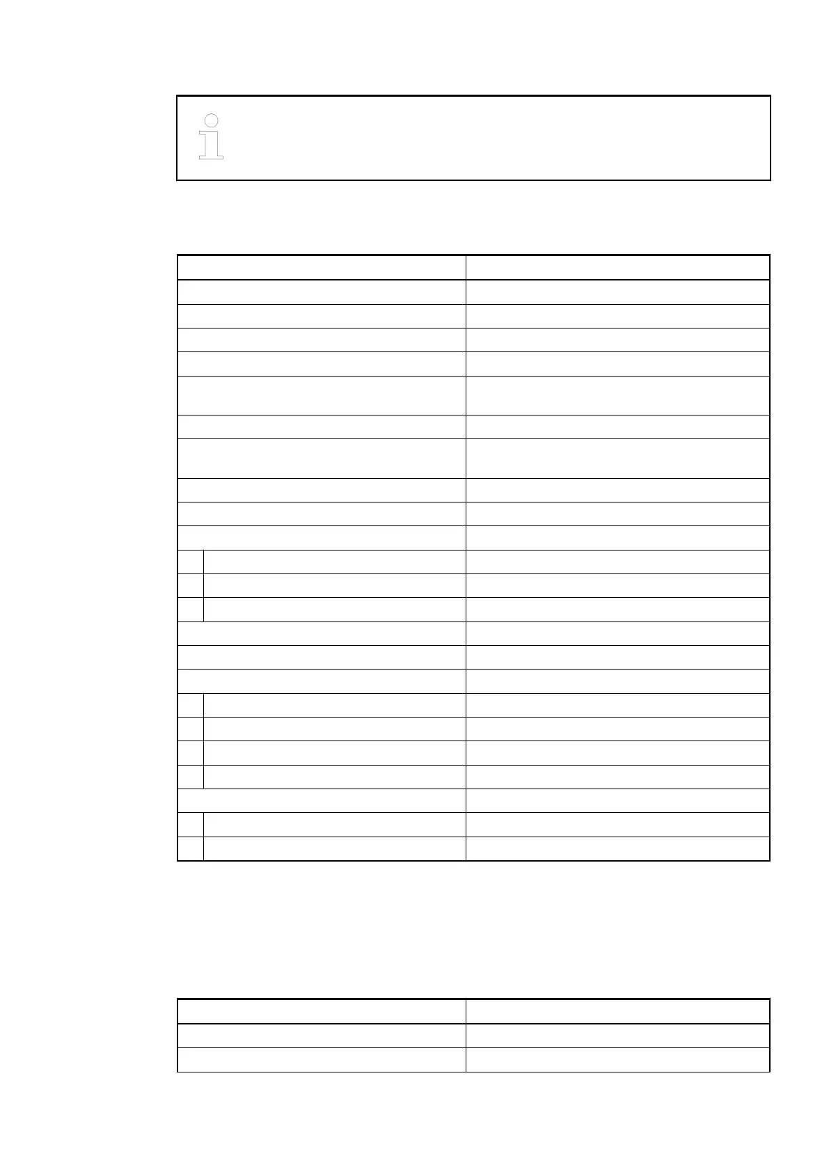
Technical Data of the Digital Inputs
Parameter Value
Number of channels per module 8
Distribution of the channels into groups 1 group of 8 channels
Terminals of the channels I0 to I7 2.0 to 2.7
Terminals of the channels C8 to C23 3.0 to 4.7
Reference potential for all inputs Terminals 1.9...4.9 (Minus pole of the process
supply voltage, signal name ZP)
Electrical isolation From the CS31 system bus
Indication of the input signals 1 yellow LED per channel, the LED is ON when
the input signal is high (signal 1)
Input type acc. to EN 61131-2 Type 1
Input delay (0->1 or 1-> 0) Typ. 8 ms, configurable from 0.1 to 32 ms
Input signal voltage 24 V DC
Signal 0 -3 V...+5 V
Undefined signal > +5 V...< +15 V
Signal 1 +15 V...+30 V
Ripple with signal 0 Within -3 V...+5 V
Ripple with signal 1 Within +15 V...+30 V
Input current per channel
Input voltage +24 V Typ. 5 mA
Input voltage +5 V > 1 mA
Input voltage +15 V > 2 mA
Input voltage +30 V < 8 mA
Max. cable length
Shielded 1000 m
Unshielded 600 m
Technical Data of the Configurable Digital Inputs/Outputs
Each of the configurable I/O channels is defined as input or output by the user program. This is
done by interrogating or allocating the corresponding channel.
Parameter Value
Number of channels per module 16 inputs/outputs (with transistors)
Distribution of the channels into groups 1 group of 16 channels
Communication Interface Modules (S500) > CS31
2019/04/173ADR010121, 13, en_US824