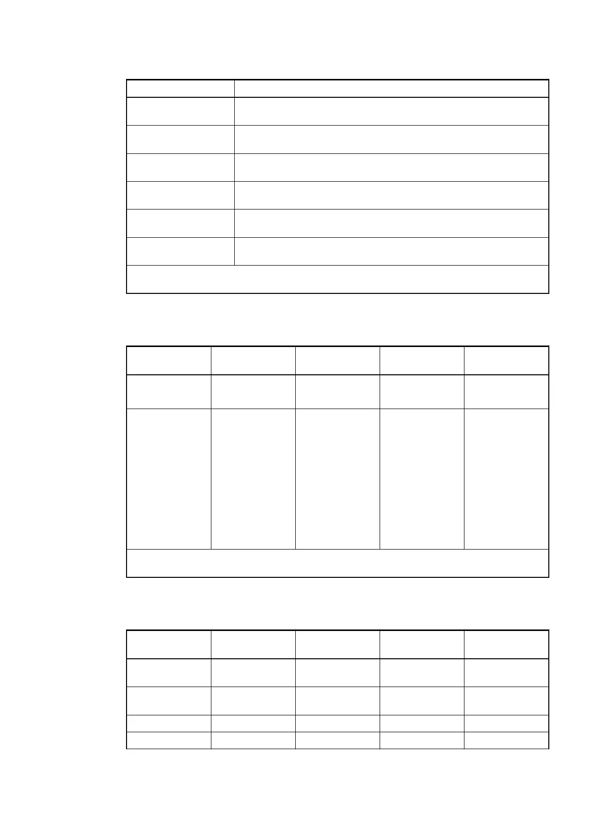
Table 111: Settings "Error LED / Failsafe function"
Setting Description
On Error LED (S-ERR) lights up at errors of all error classes, failsafe
mode off
Off by E4 Error LED (S-ERR) lights up at errors of error classes E1, E2 and E3,
failsafe mode off
Off by E3 Error LED (S-ERR) lights up at errors of error classes E1 and E2, fail-
safe mode off
On +Failsafe Error LED (S-ERR) lights up at errors of all error classes, failsafe
mode on *)
Off by E4 + Failsafe Error LED (S-ERR) lights up at errors of error classes E1, E2 and E3,
failsafe mode on *)
Off by E3 + Failsafe Error LED (S-ERR) lights up at errors of error classes E1 and E2, fail-
safe mode on *)
*) The parameters Behavior analog outputs at communication error and Behavior digital out-
puts at communication error are only evaluated if the failsafe function is enabled.
Group Parameters for the Analog Part
Name Value Internal value Internal value,
type
Default
Analog data
format
Standard
Reserved
0
255
BYTE 0
Behavior analog
outputs at com-
munication error
*)
Off
Last value
Last value 5 s
Last value 10 s
Substitute value
Substitute value
5 s
Substitute value
10 s
0
1
6
11
2
7
12
BYTE 0
*) The parameter behavior analog outputs at communication error is only analyzed if the fail-
safe mode is ON.
Channel parameters for the Analog Inputs (4x)
Name Value Internal value Internal value,
type
Default
Input 0, Channel
configuration
Operation modes
of analog inputs
Operation modes
of analog inputs
BYTE 0
Input 0, Check
channel
Settings channel
monitoring
Settings channel
monitoring
BYTE 0
: : : : :
: : : : :
Communication Interface Modules (S500) > CANopen
2019/04/173ADR010121, 13, en_US722