2.0
1.0
I0+
I0–
2.1
1.1
I1+
I1–
2.2
1.2
I2+
I2–
2.3
1.3
I3+
I3–
2.4
1.4
I4+
I4–
2.5
1.5
I5+
I5–
2.6
1.6
I6+
I6–
2.7
1.7
I7+
I7–
O0+
O0–
4.0
3.0
O4+
O4–
4.4
3.4
O1+
O1–
4.1
3.1
O5+
O5–
4.5
3.5
O2+
O2–
4.2
3.2
O6+
O6–
4.6
3.6
O3+
O3–
4.3
3.3
O7+
O7–
4.7
3.7
AGND
AGND
UP
ZP
1.8 2.8 3.8 4.8
1.9 2.9 3.9 4.9
+24 V
0 V
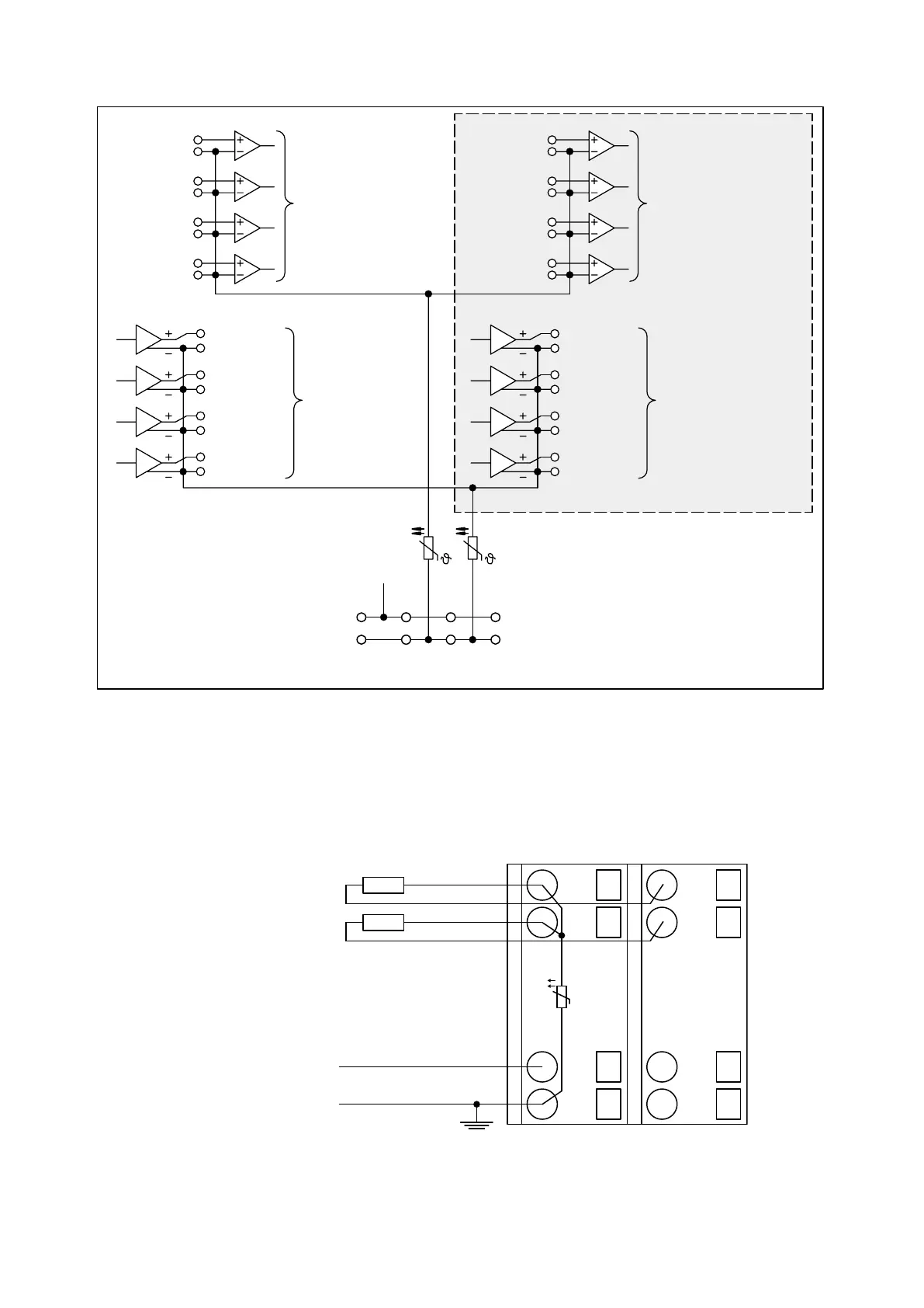
4 analog inputs
for 0...10 V,
–10 V...+10 V,
0/4... 20 mA,
Pt100 / Pt1000,
Ni1000 and
digital signals
4 analog
outputs for
–10 V...+10 V,
0/4... 20 mA
4 analog
outputs for
–10 V...+10 V
PTCPTC
4 analog inputs
for 0...10 V,
–10 V...+10 V,
0/4... 20 mA,
Pt100 / Pt1000,
Ni1000 and
digital signals
These I/Os only with AX522
Attention:
By installing equipotential
bonding conductors between
system, it must be made sure
that the potential difference
between ZP and AGND never
the different parts of the
can exceed 1 V.
Attention:
The process voltage must be
included in the earthing concept
of the control system
(e.g. earthing the minus pole).
Fig. 69: Terminal assignment
Connection of Resistance Thermometers in 2-wire Configuration
When resistance thermometers (Pt100, Pt1000, Ni1000) are used, a constant current must flow
through them to build the necessary voltage drop for the evaluation. For this, the I/O module
provides a constant current source which is multiplexed over the 8 analog channels.
UP
ZP
1.0
I0-
1.1
I1-
1.8
UP
1.9
ZP
PTC
2.0
I0+
2.1
I1+
2.8
UP
2.9
ZP
Pt100
Pt1000
Ni1000
Fig. 70: Connection example
I/O Modules > Analog I/O Modules
2019/04/173ADR010121, 13, en_US548