2.0
AI0+
2.1
AI1+
2.2
AI2+
2.3
AI3+
2.4
AI-
2.5
AO0+
2.6
AO1+
2.7
AO-
2.8
UP
2.9
ZP
24 V DC
-
+
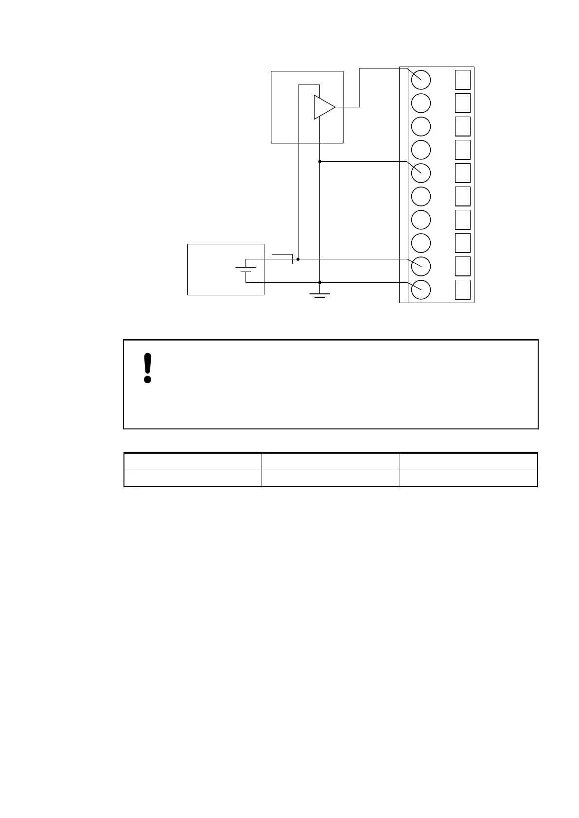
-10 ... +10 V
0 ... +10 V
Fig. 123: Connection of active-type sensors (voltage) with no electrically isolated power supply
to the analog inputs
NOTICE!
Risk of faulty measurements!
The negative pole/earthing potential at the sensors must not have too large a
potential difference with respect to ZP (max. ± 1 V within the full signal range).
Make sure that the potential difference never exceeds ± 1 V.
Voltage 0...10 V 1 channel used
Voltage -10 V...+10 V 1 channel used
For the measuring ranges that can be configured, plese refer to the sections Measuring Ranges
Ä
Chapter 1.7.1.2.10 “Measuring Ranges” on page 731 and Parameterization
Ä
Chapter
1.7.1.2.7 “Parameterization” on page 721.
To avoid error messages, configure unused analog input channels as "unused".
Connection of Passive-type Analog Sensors (Current) to the Analog Inputs
The following figure shows the connection of passive-type analog sensors (current) to the
analog input AI0. Proceed with the analog inputs AI1 to AI3 in the same way.
Communication Interface Modules (S500) > CANopen
2019/04/173ADR010121, 13, en_US716