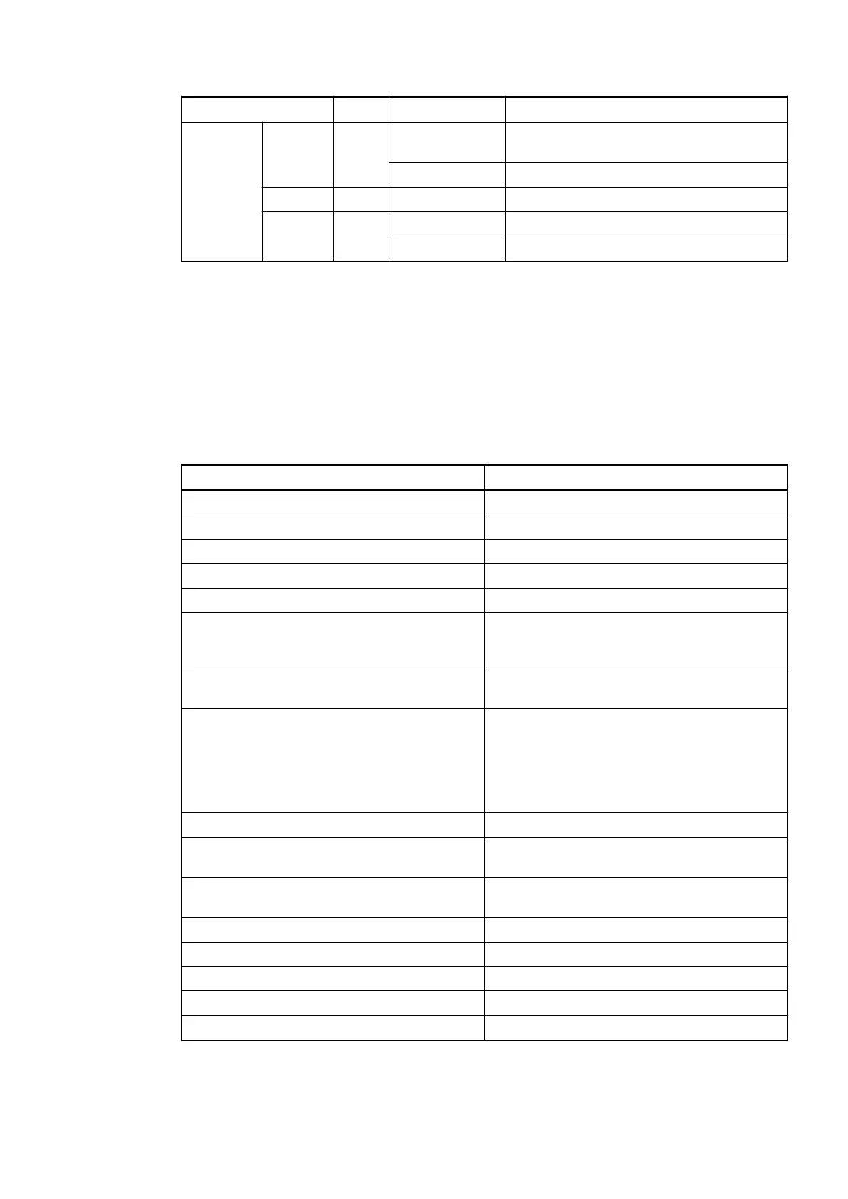
LED Color State Description
Flashes
cyclically
Protocol error occurred
OFF No communication
STA Yellow Flashes Traffic detected
ERR Red ON Error
OFF No error
1.3.2.4 Technical Data
The System Data of AC500 and S500
Ä
Chapter 2.6.1 “System Data AC500” on page 1248 are
valid for standard version.
The System Data of AC500-XC
Ä
Chapter 2.7.1 “System Data AC500-XC” on page 1309 are
valid for the XC version.
Only additional details are therefore documented below.
Parameter Value
Interface Serial interface
Transmission rate 2.4 kbit/s to 19.2 kbit/s
Protocol RCOM/RCOM+
Interface connector MC 0.5/9-G-2.5, 9-pin, male
Processor PowerPC
Usable CPUs
PM57x, PM58x, PM59x
Ä
Chapter 1.2.2.1
“PM57x (-y), PM58x (-y) and PM59x (-y)”
on page 65
Usable terminal bases
All TB5xx
Ä
Chapter 1.1.1 “TB51x-TB54x”
on page 4
Ambient temperature see:
System data AC500
Ä
Chapter 2.6.1 “System
Data AC500” on page 1248
System Data AC500 XC
Ä
Chapter 2.7.1
“System Data AC500-XC” on page 1309
Communication module bus Dual-port memory, 8 kByte
Internal power supply Through the communication module bus of
the terminal base
Current consumption from 24 VDC power
supply at the terminal base of the CPU
Typ. 80 mA
Internal RAM memory 256 kByte
External RAM memory -
External flash memory 512 kByte (firmware)
State display PWR, RDY, RUN, STA, ERR
Weight Ca. 150 g
Communication Modules (AC500 Standard) > CM574-RCOM for RCOM/RCOM+
2019/04/173ADR010121, 13, en_US98