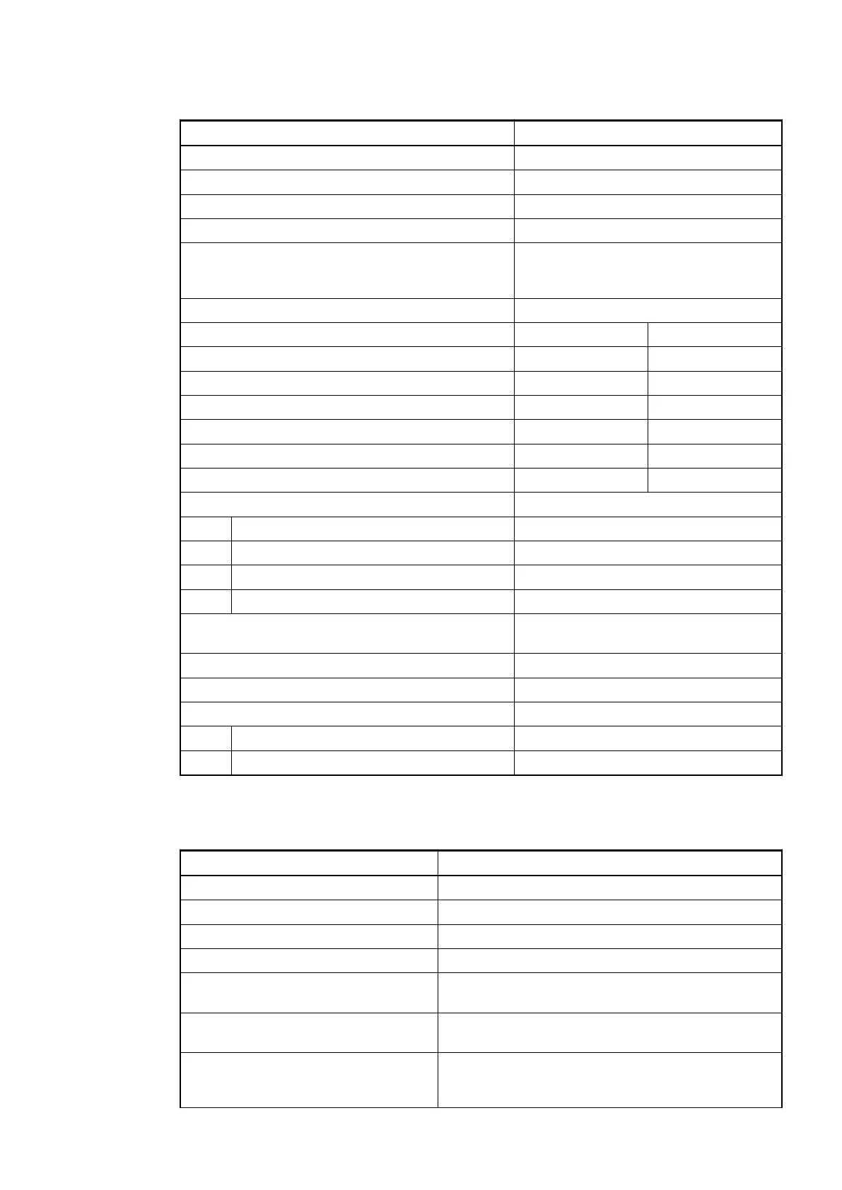
Technical Data of the Digital Inputs
Parameter Value
Number of channels per module 8
Distribution of the channels into groups 1 group for 8 channels
Connections of the channels I0 to I7 Terminals 2 to 9
Reference potential for the channels I0 to I7 Terminal 1
Indication of the input signals 1 yellow LED per channel; the LED is
ON when the input signal is high (signal
1)
Monitoring point of input indicator LED is part of the input circuitry
Input type according to EN 61131-2 Type 1 source Type 1 sink
Input signal range -24 VDC +24 VDC
Signal 0 -5 V...+3 V -3 V...+5 V
Undefined signal -15 V...+ 5 V +5 V...+15 V
Signal 1 -30 V...-15 V +15 V...+30 V
Ripple with signal 0 -5 V...+3 V -3 V...+5 V
Ripple with signal 1 -30 V...-15 V +15 V...+30 V
Input current per channel
Input voltage +24 V Typ. 5 mA
Input voltage +5 V Typ. 1 mA
Input voltage +15 V > 2.5 mA
Input voltage +30 V < 8 mA
Max. permissible leakage current (at 2-wire prox-
imity switches)
1 mA
Input delay (0->1 or 1->0) Typ. 8 ms
Input data length 1 byte
Max. cable length
Shielded 500 m
Unshielded 300 m
Technical Data of the Digital Outputs
Parameter Value
Number of channels per module 8 normally-open relay outputs
Distribution of the channels into groups 2 (4 channels per group)
Connection of the channels O0 to O3 Terminals 10 to 13
Connection of the channels O4 to O7 Terminals 15 to 18
Reference potential for the channels
O0 to O3
Terminal 14 (signal name R0..3)
Reference potential for the channels
O4 to O7
Terminal 19 (signal name R4..7)
Relay coil power supply Terminal 20 (positive pole of the process supply
voltage, signal name L+). The negative pole is pro-
vided by the I/O bus.
I/O Modules > Digital I/O Modules
2019/04/17 3ADR010121, 13, en_US 295