Parameter Value
Reference potential for all outputs Terminals 1.9...3.9 (minus pole of the supply
voltage, signal name ZP)
Common power supply voltage For all outputs terminal 3.8 (plus pole of the
supply voltage, signal name UP3)
Output voltage for signal 1 UP3 (-0.8 V)
Output delay (0->1 or 1->0) On request
Output current
Rated value per channel 500 mA at UP3 = 24 V
Max. value (all channels together) 4 A
Leakage current with signal 0 < 0.5 mA
Fuse for UP3 10 A fast
Demagnetization with inductive DC load Via internal varistors (see figure below this
table)
Output switching frequency
With resistive load On request
With inductive loads Max. 0.5 Hz
With lamp loads 11 Hz max. at 5 W max.
Short-circuit-proof / overload-proof Yes
Overload message (I > 0.7 A) Yes, after ca. 100 ms
Output current limitation Yes, automatic reactivation after short circuit/
overload
Resistance to feedback against 24V signals Yes (software-controlled supervision)
Max. cable length
Shielded 1000 m
Unshielded 600 m
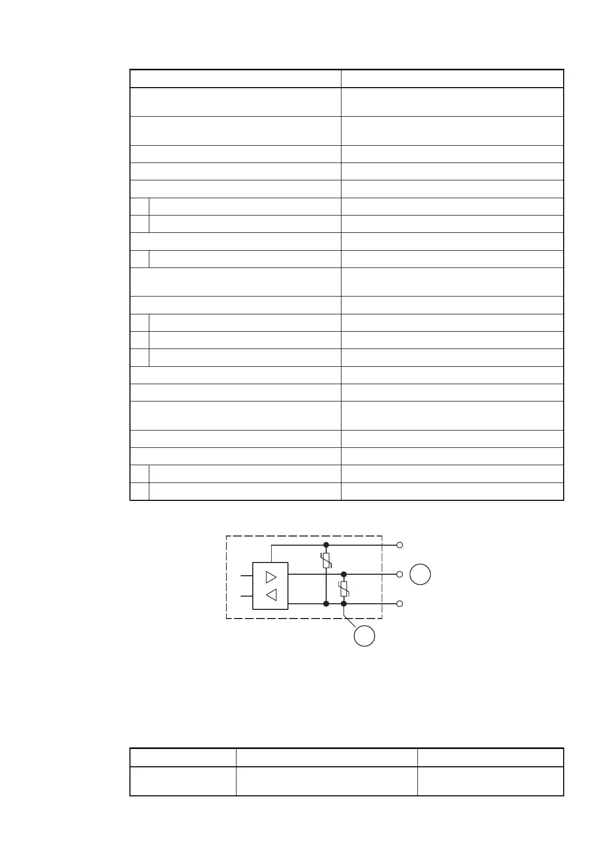
The following drawing shows the circuitry of a digital input/output with the varistors for demag-
netization when inductive loads are switched off.
Fig. 172: Digital input/output (circuit diagram)
1 Digital input/output
2 For demagnetization when inductive loads are turned off
1.7.3.2.12 Ordering Data
Part No. Description Product Life Cycle Phase *)
1SAP 221 000 R0001 CI512-ETHCAT, EtherCAT bus
module, 8 DI, 8 DO and 8 DC
Active
Communication Interface Modules (S500) > EtherCAT
2019/04/173ADR010121, 13, en_US876