All available inputs/outputs are electrically isolated from all other circuitry of the module. There
is no potential separation between the channels within the same group.
For use in extreme ambient conditions (e.g. wider temperature and humidity range), a special
XC version of the device is available.
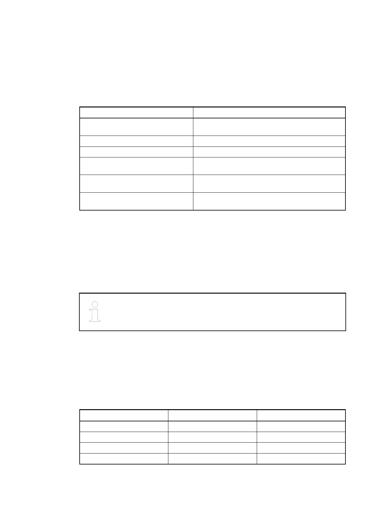
Functionality
Parameter Value
Fast counter Integrated, many configurable operating modes (only
with AC500)
LED displays For signal states, errors and supply voltage
Internal power supply Via the expansion bus interface (I/O bus)
External power supply Via the terminals ZP and UP (process voltage
24 VDC)
Required terminal units
TU515 or TU516
Ä
Chapter 1.4.3 “TU515, TU516,
TU516-H and TU542 for I/O Modules” on page 153
Effect of incorrect input terminal con-
nection
Wrong or no signal detected, no damage up to 35 V
The device is plugged on a terminal unit
Ä
Chapter 1.4.3 “TU515, TU516, TU516-H and TU542
for I/O Modules” on page 153. Position the module properly and press until it locks in place. The
terminal unit is either mounted on a DIN rail or to the wall using 2 screws plus the additional
accessory for wall mounting (TA526
Ä
Chapter 1.8.2.4 “TA526 - Wall Mounting Accessory”
on page 1152).
Electrical Connection
For a detailed description of the mounting, disassembly and electrical connec-
tion of the module, please refer to the System Assembly, Construction and Con-
nection chapter
Ä
Chapter 2.6 “AC500 (Standard)” on page 1248.
The electrical connection of the I/O channels is carried out using the 40 terminals of the I/O ter-
minal unit. I/O modules can be replaced without re-wiring the terminal units.
The terminals 1.8 to 4.8 and 1.9 to 4.9 are electrically interconnected within the I/O terminal unit
and have always the same assignment, irrespective of the inserted module:
Terminals 1.8 to 4.8: process voltage UP = +24 VDC
Terminals 1.9 to 4.9: process voltage ZP = 0 VDC
Table 50: Assignment of the other terminals:
Terminals Signal Description
1.0 to 1.7 I0 to I7 8 digital inputs
2.0 to 2.7 I8 to I15 8 digital inputs
3.0 to 3.7 I16 to I23 8 digital inputs
4.0 to 4.7 I24 to I31 8 digital inputs
The internal power supply voltage for the module's circuitry is carried out via the I/O bus (pro-
vided by a bus module or a CPU). Thus, the current consumption from 24 VDC power supply at
the terminals L+/UP and M/ZP of the CPU/bus module increases by 2 mA per DI524.
I/O Modules > Digital I/O Modules
2019/04/173ADR010121, 13, en_US344