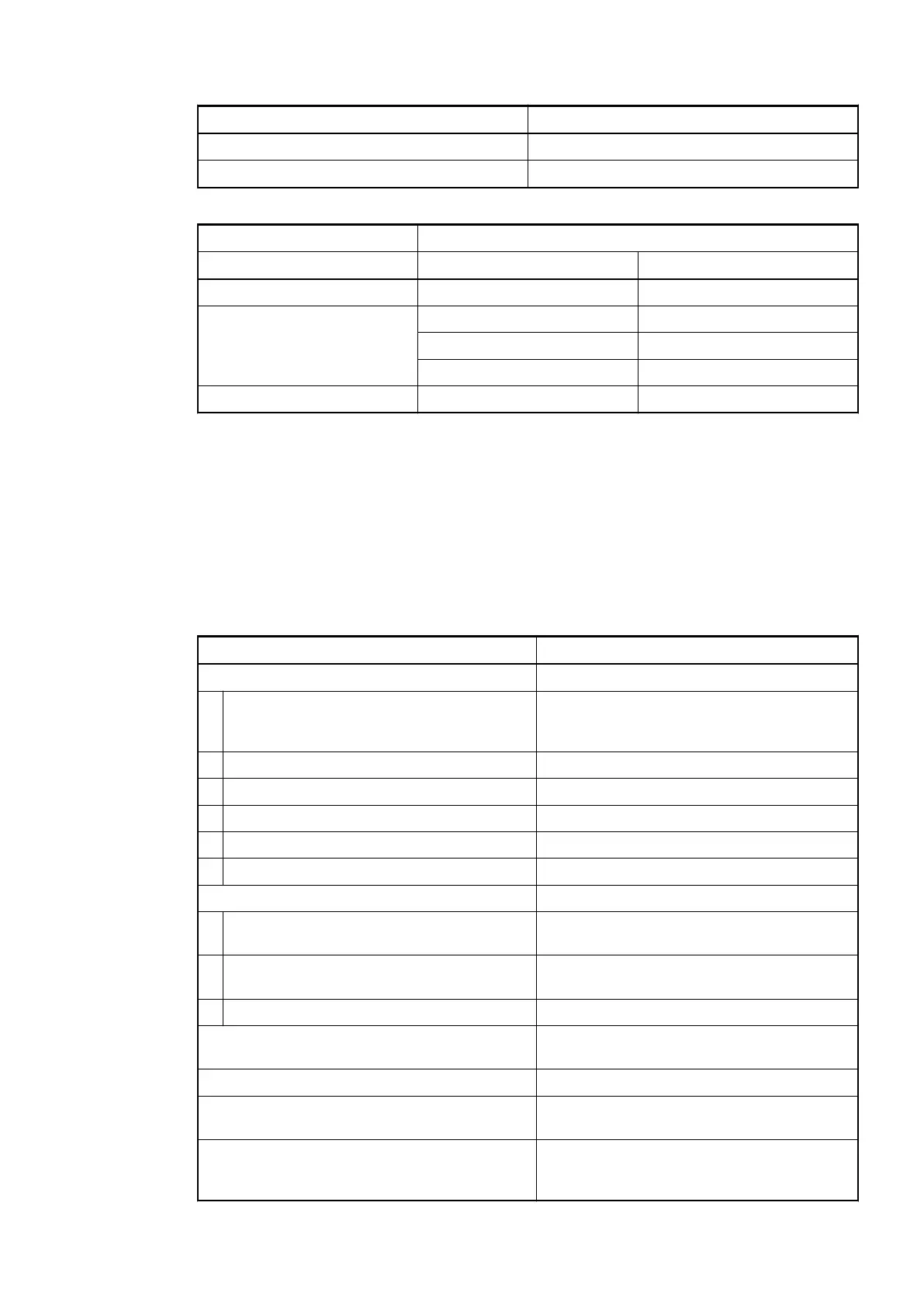
Range Value
-40 °C
Underflow < -40 °C
Range Digital value
Decimal Hex.
Overflow 32767 7FFF
Normal range 850 0352
0 0000
-400 FE70
Underflow -32768 8000
Technical Data
The System Data of AC500 and S500
Ä
Chapter 2.6.1 “System Data AC500” on page 1248 are
valid for standard version.
The System Data of AC500-XC
Ä
Chapter 2.7.1 “System Data AC500-XC” on page 1309 are
valid for the XC version.
Only additional details are therefore documented below.
Parameter Value
Process voltage
Connections Terminals 1.8, 2.8, 3.8 and 4.8 for +24 V
(UP) as well as 1.9, 2.9, 3.9 and 4.9 for 0 V
(ZP)
Rated value 24 VDC
Max. ripple 5 %
Protection against reversed voltage Yes
Rated protection fuse on UP 10 A fast
Galvanic isolation Yes, per module
Current consumption
From 24 VDC power supply at the terminals
UP/L+ and ZP/M of the CPU/bus module
Ca. 2 mA
Current consumption from UP in normal
operation
130 mA
Inrush current from UP (at power up) On request
Max. length of analog cables, conductor cross
section > 0.14 mm²
100 m
Weight 130 g
Mounting position Horizontal or vertical with derating (max.
temperature 40 °C)
Cooling The natural convection cooling must not be
hindered by cable ducts or other parts in the
switch-gear cabinet.
I/O Modules > Analog I/O Modules
2019/04/173ADR010121, 13, en_US502