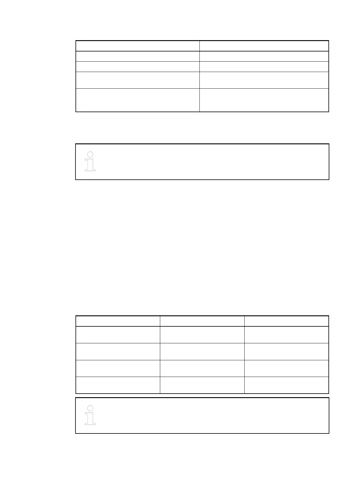
Parameter Value
LED displays 19 LEDs for signals and error messages
Internal power supply Through the expansion bus interface (I/O bus)
External power supply Via the terminals ZP and UP (process voltage
24 VDC)
Required terminal unit
TU515 or TU516
Ä
Chapter 1.4.3 “TU515,
TU516, TU516-H and TU542 for I/O Modules”
on page 153
Electrical Connection
For a detailed description of the mounting, disassembly and electrical connec-
tion of the module, please refer to the System Assembly, Construction and Con-
nection chapter
Ä
Chapter 2.6 “AC500 (Standard)” on page 1248.
The modules are plugged on an I/O terminal unit
Ä
Chapter 1.4.3 “TU515, TU516, TU516-H
and TU542 for I/O Modules” on page 153. Properly position the modules and press until they
lock in place. The terminal units are mounted on a DIN rail or with 2 screws plus the additional
accessory for wall mounting (TA526
Ä
Chapter 1.8.2.4 “TA526 - Wall Mounting Accessory”
on page 1152).
The electrical connection of the I/O channels is carried out using the 40 terminals of the I/O ter-
minal unit. I/O modules can be replaced without re-wiring the terminal units.
The terminals 1.8 to 4.8 and 1.9 to 4.9 are electrically interconnected within the I/O terminal
units and have always the same assignment, independent of the inserted module:
Terminals 1.8 to 4.8: process voltage UP = +24 VDC
Terminals 1.9 to 4.9: process voltage ZP = 0 VDC
The assignment of the other terminals:
Terminals Signal Description
1.0 to 1.7 O0- to O7- Negative poles of the first 8
analog outputs
2.0 to 2.7 O0+ to O7+ Positive poles of the first 8
analog outputs
3.0 to 3.7 O8- to O15- Negative poles of the fol-
lowing 8 analog outputs
4.0 to 4.7 O8+ to O15+ Positive poles of the following
8 analog outputs
For the open-circuit detection (cut wire), each analog input channel is pulled up
to "plus" by a high-resistance resistor. If nothing is connected, the maximum
voltage will be read in then.
The internal power supply voltage for the module's circuitry is carried out via the I/O bus (pro-
vided by a bus module or a CPU). Thus, the current consumption from 24 VDC power supply at
the terminals L+/UP and M/ZP of the CPU/bus module increases by 2 mA per AO523.
I/O Modules > Analog I/O Modules
2019/04/17 3ADR010121, 13, en_US 507