3.0
3.1
3.2
3.3
3.4
3.5
3.6
3.7
3.8
3.9
2.0
2.1
2.2
2.3
2.4
2.5
2.6
2.7
2.8
2.9
1.0
1.1
1.2
1.3
1.4
1.5
1.6
1.7
1.8
1.9
4.0
4.1
4.2
4.3
4.4
4.5
4.6
4.7
4.8
4.9
CI581
CH-ERR1
CH-ERR3
CH-ERR2
2.4
2.0 AI0+
2.2 AI2+
2.7
AO-
2.9
ZP
2.3 AI3+
2.1 AI1+
AI -
2.5
AO0+
2.6
AO1+
2.8
UP
4.0
DO0
4.2
DO2
4.4
DO4
4.6
DO6
4.9
ZP
4.1
DO1
4.3
DO3
4.5
DO5
4.7
DO7
4.8 UP3
3.8
UP
3.9
ZP
3.0 DI0
3.2 DI2
3.3 DI3
3.5
DI5
3.6 DI6
3.4
DI4
3.7
DI7
3.1 DI1
UP 24VDC 100W
CANopen Slave
4AI 2AO 8DI 8DO
Input 24VDC/Output 24VDC 0.5A
PWR/
RUN
ADDR x01H
ADDR x10H
4
C
3
B
2
A
1
9
0
8
F
7
E
6
D
5
4
C
3
B
2
A
1
9
0
8
F
7
E
6
D
5
1.8
GND
1.9
GND
1.0 CAN+
1.2 CAN-
1.3 CAN-
1.5
Term+
1.6 Term-
1.4
Term+
1.7
Term-
1.1 CAN+
CN-
RUN
CN-
ERR
S-
ERR
I/O-
Bus
12
3
4
5
6
7
8
9
10
12
13
11
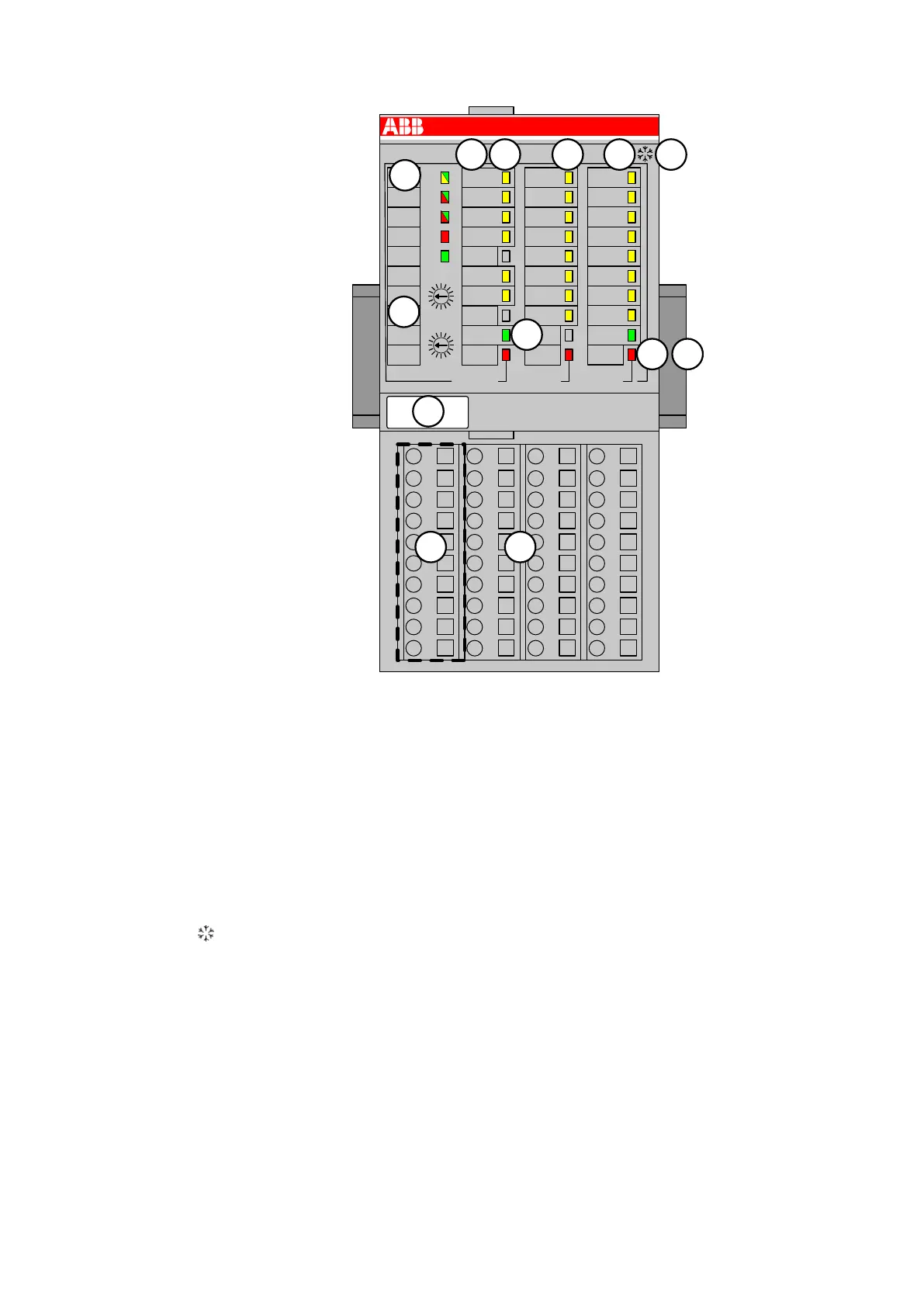
1 I/O bus
2 Allocation between terminal No. and signal name
3 6 yellow LEDs to display the signal states of the analog inputs/outputs (AI0 - AI3, AO0 -
AO1)
4 8 yellow LEDs to display the signal states of the digital inputs (DI0 - DI7)
5 8 yellow LEDs to display the signal states of the digital outputs (DO0 - DO7)
6 2 green LEDs to display the supply voltage UP and UP3
7 3 red LEDs to display errors (CH-ERR1, CH-ERR2, CH-ERR3)
8 5 System LEDs: PWR/RUN, CN-RUN, CN-ERR, S-ERR, I/O-Bus
9 Label
10 2 rotary switches for setting the CANopen Node ID
11 10 terminals to connect the CANopen bus signals
12 Terminal unit
13 DIN rail
Sign for XC version
1.7.1.2.1 Intended Purpose
The CANopen bus module CI581-CN is used as decentralized I/O module in CANopen net-
works. Depending on the used terminal unit the network connection is performed either via 9-pin
female D-sub connector or via 10 terminals (screw or spring terminals) which are integrated in
the terminal unit. The bus module contains 22 I/O channels with the following properties:
● 4 analog inputs (2.0...2.3)
● 2 analog outputs (2.5...2.6)
● 8 digital inputs 24 VDC in 1 group (3.0...3.7)
● 8 digital outputs 24 VDC in 1 group (4.0...4.7)
Communication Interface Modules (S500) > CANopen
2019/04/17 3ADR010121, 13, en_US 701