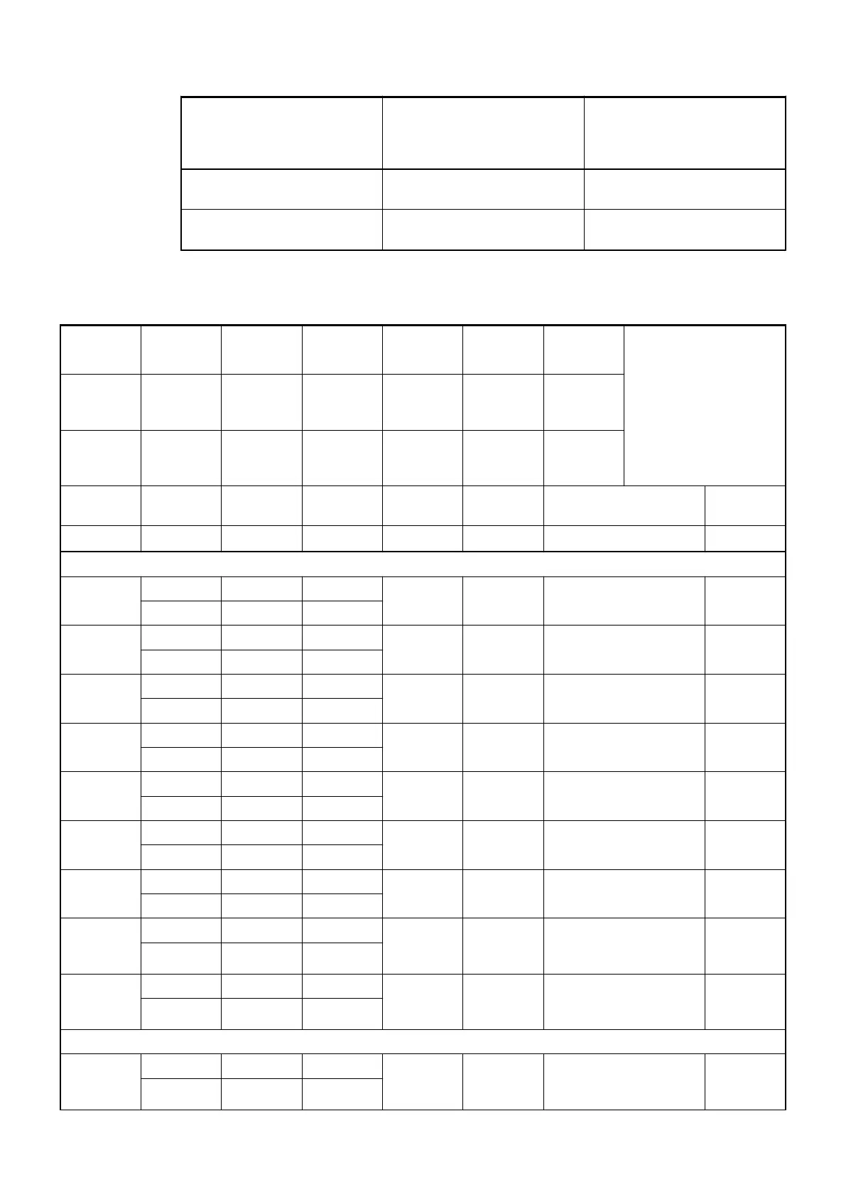
Intended behaviour of
output channel when the
control system stops
Required setting of the
module parameter "Behav-
iour of outputs in case of a
communication error"
Required setting of the
channel parameter "Substi-
tute value"
Substitute value for 5 s and
then turn off
Substitute value 5 sec Depending on configuration
Substitute value for 10 s and
then turn off
Substitute value 10 sec Depending on configuration
Diagnosis
E1...E4 d1 d2 d3 d4 Identifier
000...063
AC500
display
<− Display in
Class Comp Dev Mod Ch Err PS501
PLC
browser
Byte 6
Bit 6...7
- Byte 3 Byte 4 Byte 5 Byte 6
Bit 0...5
FBP diag-
nosis
block
Class Interface Device Module Channel Error
Identifier
Error message Remedy
1
)
2
)
3
)
4
)
Module error
3 14 1...10 31 31 19 Checksum error in the
I/O module
Replace
I/O module
11 / 12 ADR 1...10
3 14 1...10 31 31 3 Timeout in the I/O
module
Replace
I/O module
11 / 12 ADR 1...10
3 14 1...10 31 31 40 Different hard-/firmware
versions in the module
Replace
I/O module
11 / 12 ADR 1...10
3 14 1...10 31 31 43 Internal error in the
module
Replace
I/O module
11 / 12 ADR 1...10
3 14 1...10 31 31 36 Internal data exchange
failure
Replace
I/O module
11 / 12 ADR 1...10
3 14 1...10 31 31 9 Overflow diagnosis
buffer
New start
11 / 12 ADR 1...10
3 14 1...10 31 31 26 Parameter error Check
master
11 / 12 ADR 1...10
3 14 1...10 31 31 11 Process voltage too low Check
process
voltage
11 / 12 ADR 1...10
4 14 1...10 31 31 45 Process voltage is
switched off (ON −>
OFF)
Process
voltage ON
11 / 12 ADR 1...10
Channel error
4 14 1...10 1 0...3
0...7
48 Analog value overflow
or broken wire at an
analog input
Check
input value
or terminal
11 / 12 ADR 1...10
I/O Modules > Analog I/O Modules
2019/04/173ADR010121, 13, en_US560