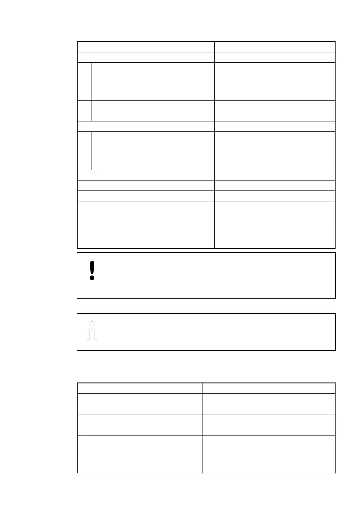
Parameter Value
Process supply voltage
Connections Terminals 1.8, 2.8, 3.8 and 4.8 for UP (+24
VDC) and 1.9, 2.9, 3.9 and 4.9 for ZP (0 V)
Protection against reverse voltage yes
Rated protection fuse at UP 10 A fast
Rated value 24 VDC
Max. ripple 5 %
Current consumption
From UP 0.07 A + max. 0.5 A per output
From 24 VDC power supply at the terminals
UP/L+ and ZP/M of the CPU/bus module
ca. 2 mA
Inrush current from UP (at power-up)
0.04 A
2
s
Galvanic isolation Yes, per module
Max. power dissipation within the module 6 W (outputs unloaded)
Weight (without terminal unit) ca. 125 g
Mounting position Horizontal mounting or vertical with
derating (output load reduced to 50% at 40
°C)
Cooling The natural convection cooling must not be
hindered by cable ducts or other parts in
the switch-gear cabinet.
NOTICE!
Attention:
All I/O channels (digital and analog) are protected against reverse polarity,
reverse supply, short circuit and continuous overvoltage up to 30 VDC.
Multiple overloads
No effects of multiple overloads on isolated multi-channel modules occur, as
every channel is protected individually by an internal smart high-side switch.
Technical Data of the Digital Outputs
Parameter Value
Number of channels per module 16 outputs (with transistors)
Distribution of the channels into groups 1 group of 16 channels
Connection of the channels
DO0 to DO7 Terminals 1.0 to 1.7
DO8 to DO15 Terminals 2.0 to 2.7
Indication of the output signals 1 yellow LED per channel, the LED is ON if the
output signal is high (signal 1)
Monitoring point of output indicator LED is controlled by process CPU
I/O Modules > Digital/Analog I/O Modules
2019/04/173ADR010121, 13, en_US628