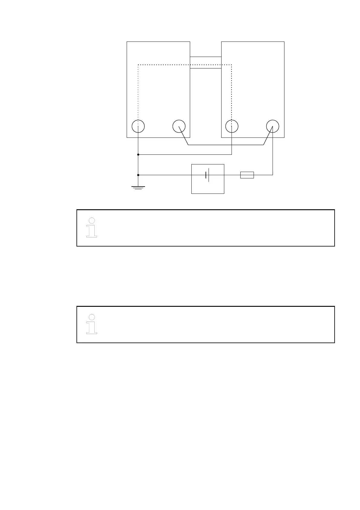
CPU /
Bus Module
24 V DC
−
+
L+ / UPM / ZP
I/O−Bus DO573
L+M
Fig. 18: Power supply - the negative connection is realized via the I/O bus
The L+ connection of the DO573 and the 24 V supply of the CPU/bus module
must be connected to the same 24 V power supply .
I/O Configuration
The module itself does not store configuration data. It receives its parameterization data from
the master device of the I/O bus (CPU or bus module) during power-up of the system.
Hence, replacing I/O modules is possible without any re-parameterization via software.
If the external power supply voltage via UP/ZP terminals fails, the I/O module
loses its configuration data. The whole station has to be switched off and on
again to re-configure the module.
Parameterization
The arrangement of the parameter data is performed with Automation Builder software.
The parameter data directly influences the functionality of modules.
For non-standard applications, it is necessary to adapt the parameters to your system configu-
ration.
I/O Modules > Digital I/O Modules
2019/04/17 3ADR010121, 13, en_US 267