10
11
NO8
NO9
13
NO11
12
NO10
14
NO12
15
NO13
16
NO14
17
NO15
18
R8..15
19
L+
20
M
1
2
NO0
NO1
4
NO3
3
NO2
5
NO4
6
NO5
7
NO6
8
NO7
9
R0..7
24 V DC
-
+
120 V AC/
240 V AC
~
L
N
120 V AC/
240 V AC
~
L
N
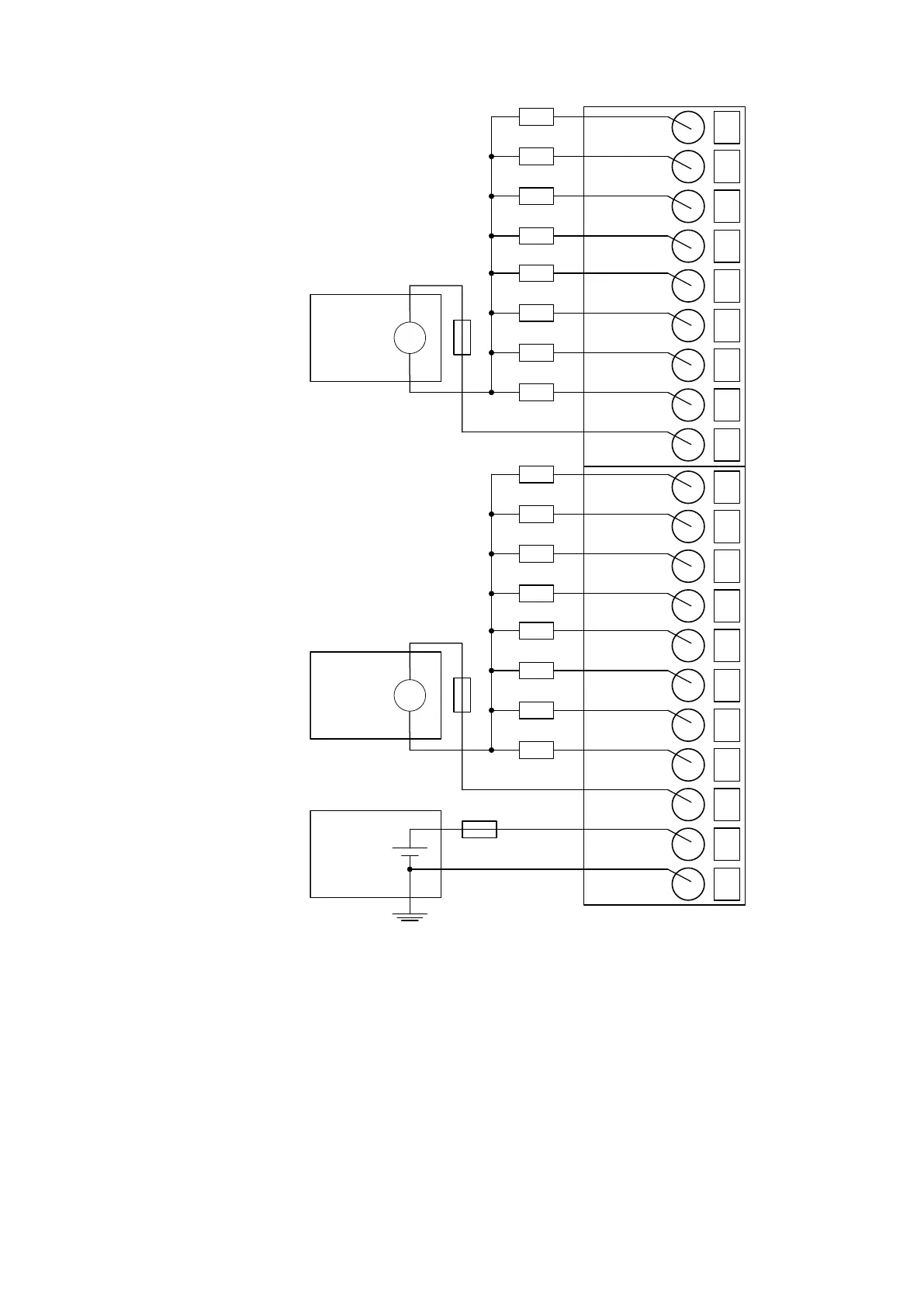
Fig. 17: Connection of 100-240 VAC actuators
The module provides several diagnosis functions (see section Diagnosis
Ä
Chapter 1.5.1.1.11.6
“Diagnosis” on page 268).
The meaning of the LEDs is described in the section State LEDs
Ä
Chapter 1.5.1.1.10.7 “State
LEDs” on page 258.
I/O Modules > Digital I/O Modules
2019/04/173ADR010121, 13, en_US266