Internal value Operating modes of the analog inputs, individually configu-
rable
19 3-wire Ni1000 -50 °C...+150 °C *)
*) In the operating modes with 3-wire configuration or with differen-
tial inputs, two adjacent analog inputs belong together (e.g. the
channels 0 and 1). In these cases, both channels are configured in
the desired operating mode. The lower address must be the even
address (channel 0). The next higher address must be the odd
address (channel 1). The converted analog value is available at
the higher address (channel 1).
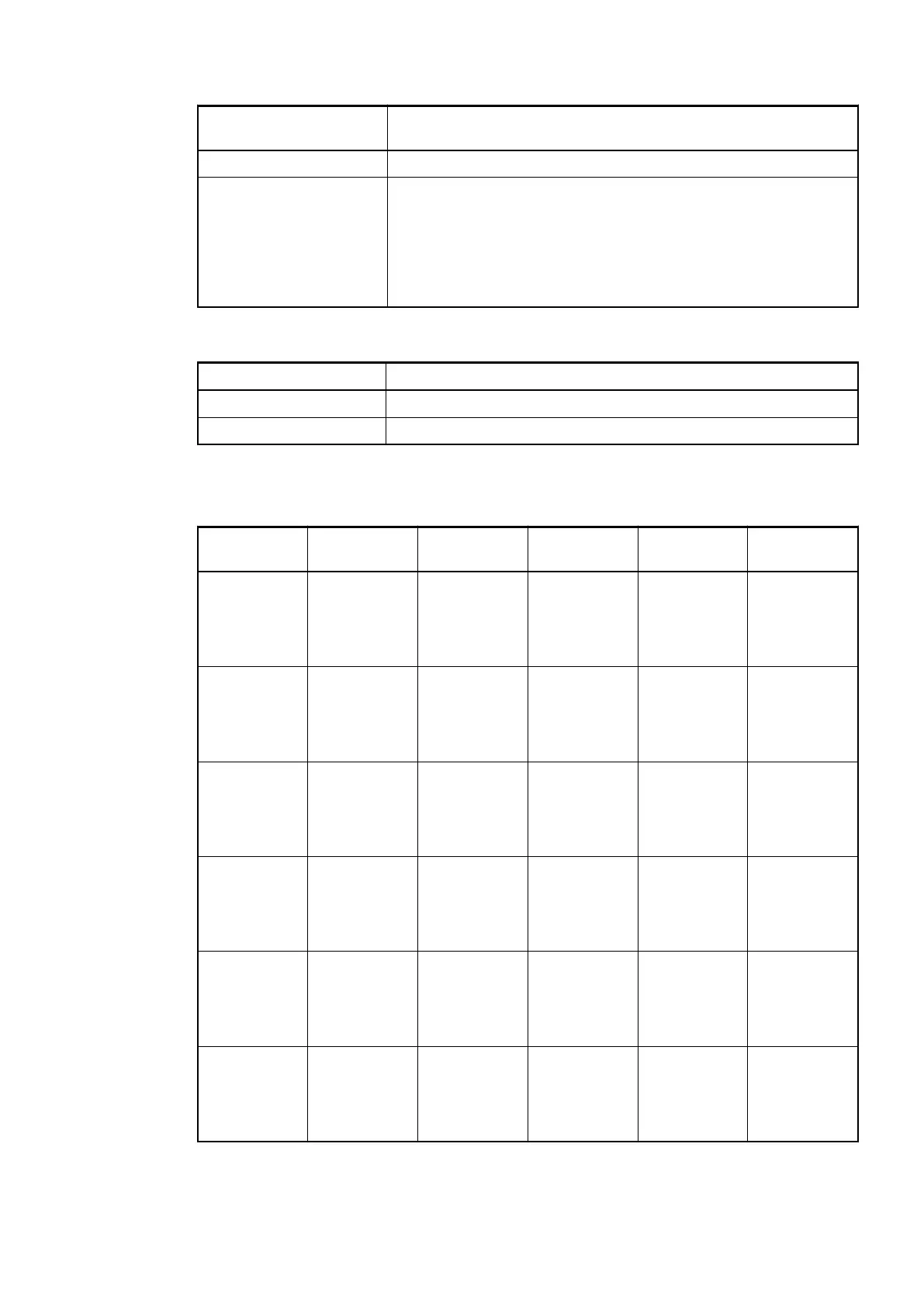
Table 89: Channel Monitoring
Internal Value Check Channel
0 (default) Plausib(ility), cut wire, short circuit
3 Not used
Channel Parameters for the Analog Outputs (2x)
Name Value Internal value Internal
value, type
Default EDS Slot /
Index
0
Output 0,
Channel con-
figuration
see
Ä
Table 90 “C
hannel Con-
figuration”
on page 622
see
Ä
Table 90 “C
hannel Con-
figuration”
on page 622
BYTE 0 0x0Y11
Output 0,
Check
channel
see
Ä
Table 91 “C
hannel Moni-
toring”
on page 622
see
Ä
Table 91 “C
hannel Moni-
toring”
on page 622
BYTE 0 0x0Y12
Output 0,
Substitute
value
see
Ä
Table 92 “S
ubstitute
Value”
on page 622
see
Ä
Table 92 “S
ubstitute
Value”
on page 622
WORD 0 0x0Y13
Output 1,
Channel con-
figuration
see
Ä
Table 90 “C
hannel Con-
figuration”
on page 622
see
Ä
Table 90 “C
hannel Con-
figuration”
on page 622
BYTE 0 0x0Y14
Output 1,
Check
channel
see
Ä
Table 91 “C
hannel Moni-
toring”
on page 622
see
Ä
Table 91 “C
hannel Moni-
toring”
on page 622
BYTE 0 0x0Y15
Output 1,
Substitute
value
see
Ä
Table 92 “S
ubstitute
Value”
on page 622
see
Ä
Table 92 “S
ubstitute
Value”
on page 622
WORD 0 0x0Y16
I/O Modules > Digital/Analog I/O Modules
2019/04/17 3ADR010121, 13, en_US 621