For a description of the functions of the LEDs, please refer to Diagnosis and displays / displays
Ä
Chapter 1.5.2.2.2.7 “Diagnosis” on page 493.
Unused input channels can be left open, because they are of low resistance.
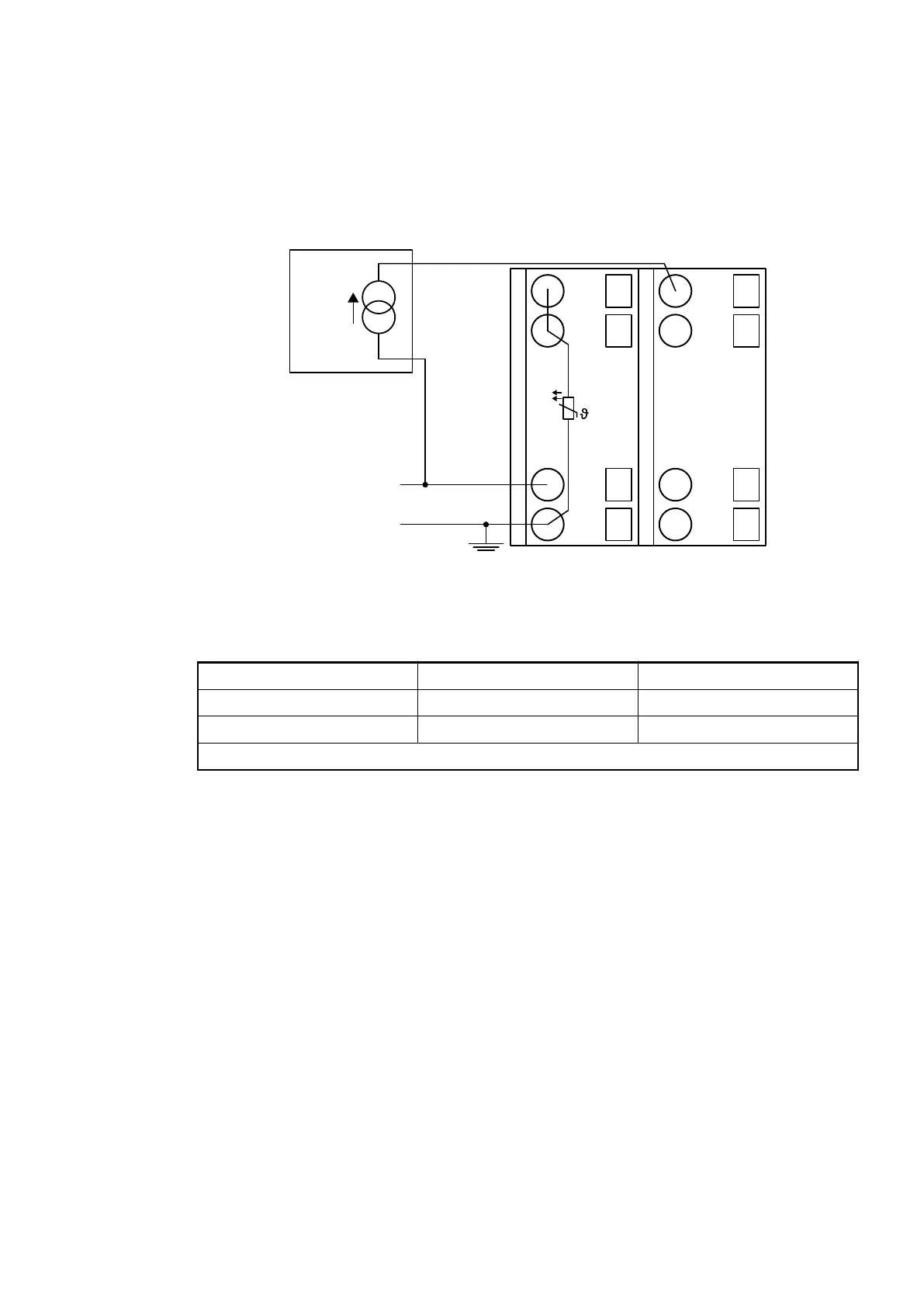
Connection of Passive-type Analog Sensors (Current)
UP
ZP
1.0
I0-
1.1
I0B
1.8
UP
1.9
ZP
PTC
2.0
I0+
2.1
I0A
2.8
UP
2.9
ZP
-
+
+4 ... +20 mA
Fig. 48: Connection example
The following measuring ranges can be configured
Ä
Chapter 1.5.2.2.2.6 “Parameterization”
on page 489:
Current -20 mA... 20 mA *) 1 channel used
Current 0 mA... 20 mA *) 1 channel used
Current 4 mA... 20 mA 1 channel used
*) This setting is not applicable with passive-type analog sensors (current).
The function of the LEDs is described under Diagnosis and displays / displays
Ä
Chapter
1.5.2.2.2.7 “Diagnosis” on page 493.
Unused input channels can be left open, because they are of low resistance.
I/O Modules > Analog I/O Modules
2019/04/173ADR010121, 13, en_US480