UP
ZP
1.2
I1-
1.3
I1B
1.8
UP
1.9
ZP
1.0
I0-
1.1
I0B
PTC
2.2
I1+
2.3
I1A
2.8
UP
2.9
ZP
2.0
I0+
2.1
I0A
-50 ... +50 mV
-500 ... +500 mV
-1 ... +1 V
-5 ... +5 V
-10 ... +10 V
0 ... +5 V
0 ... +10 V
1)
-50 ... +50 mV
-500 ... +500 mV
-1 ... +1 V
-5 ... +5 V
-10 ... +10 V
0 ... +5 V
0 ... +10 V
0 V
<= 10 V
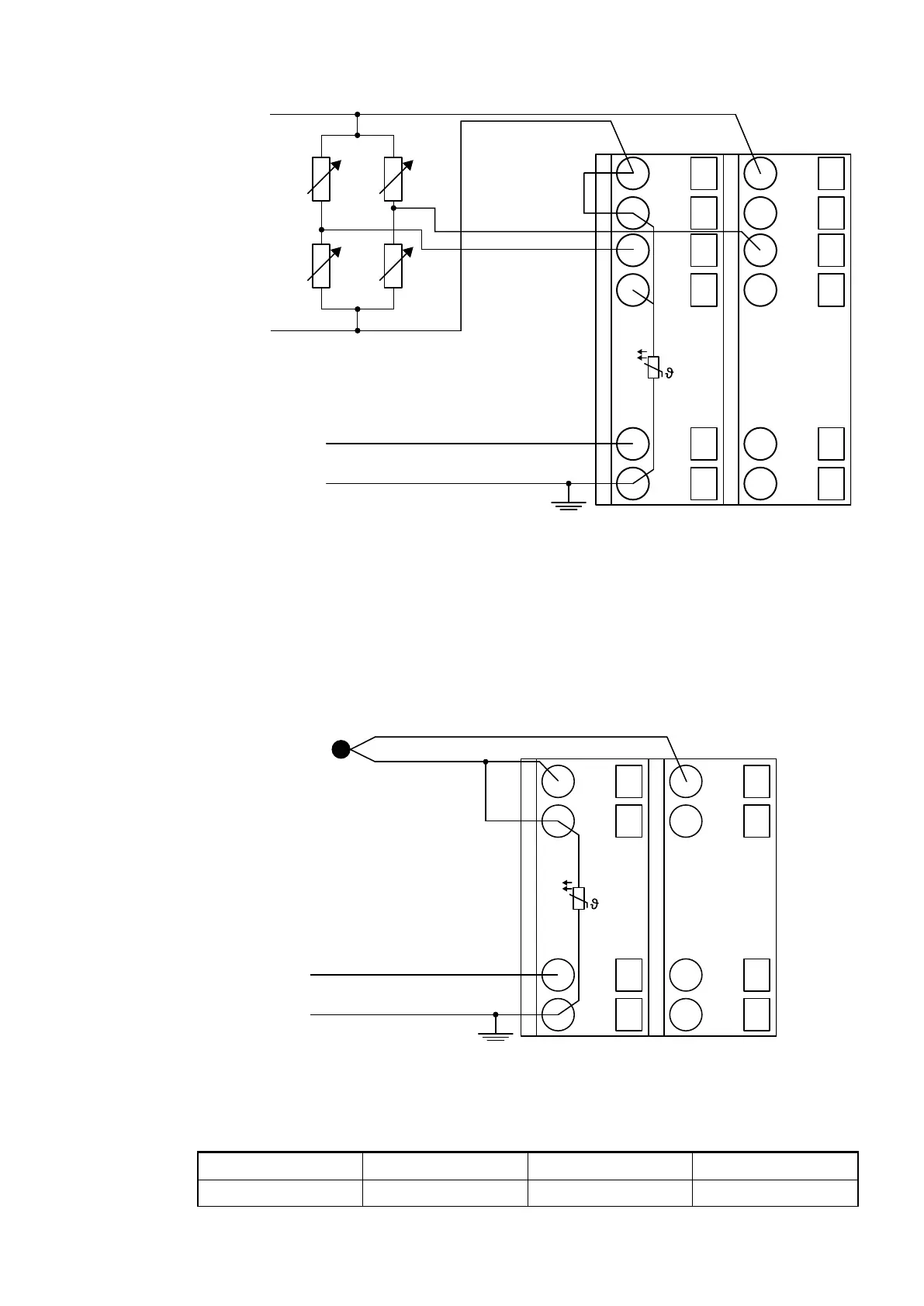
Fig. 56: Connection example
1 Bridge to IxB necessary with electrically isolated supply
All voltage measuring ranges can be configured
Ä
Chapter 1.5.2.2.2.6 “Parameterization”
on page 489 .
The calculation of the resistor deviation must be performed via the bridge voltage by the PLC
user program.
Connection of Thermocouples
PTC
1.0
I0-
1.1
I0B
1.8
UP
1.9
ZP
2.0
I0+
2.1
I0A
2.8
UP
2.9
ZP
ZP
UP
Fig. 57: Connection example
The following measuring ranges can be configured
Ä
Chapter 1.5.2.2.2.6 “Parameterization”
on page 489 :
J type -210 °C...1200 °C Fe-CuNi 1 channel used
K type -270 °C...1372 °C Ni-CrNi 1 channel used
I/O Modules > Analog I/O Modules
2019/04/17 3ADR010121, 13, en_US 487