UP
ZP
1.0
I0-
1.1
I1-
1.8
UP
1.9
ZP
PTC
2.0
I0+
2.1
I1+
2.8
UP
2.9
ZP
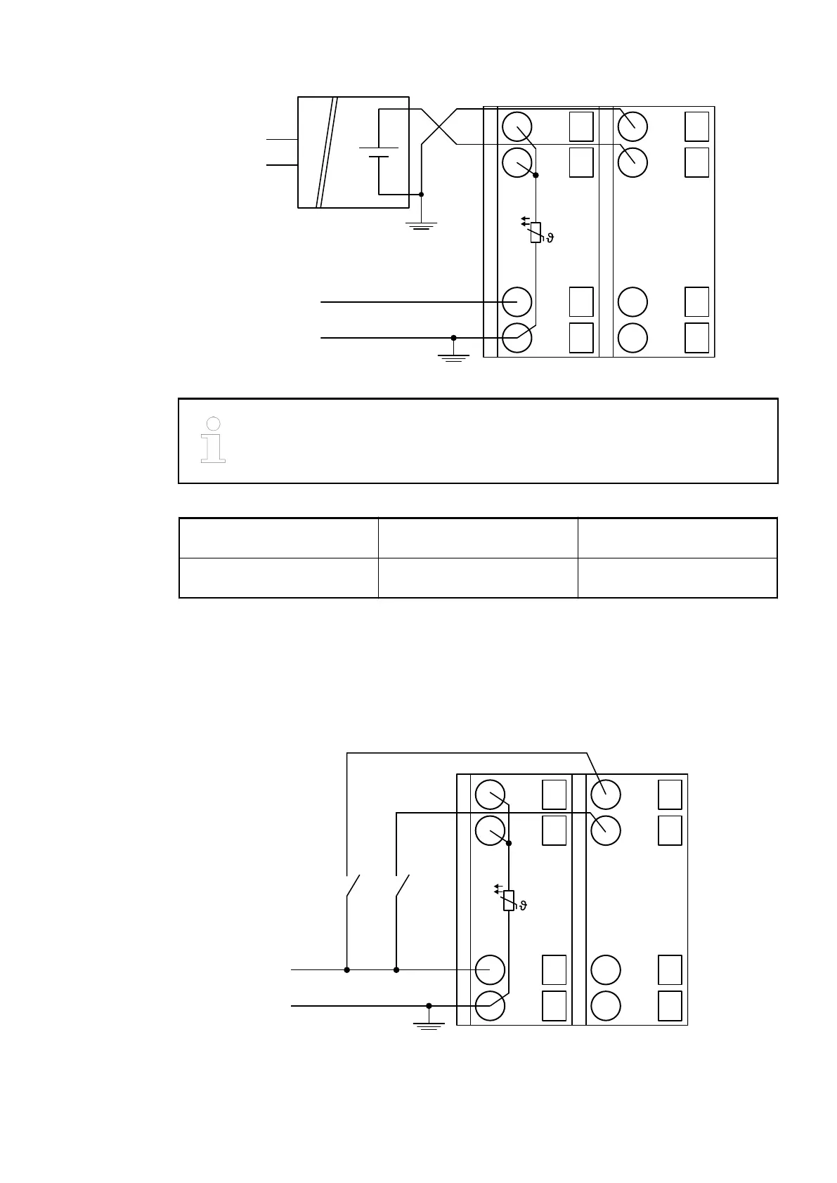
0 ... 10 V
-10 ... +10 V
+
-
U
IN
Fig. 66: Connection example
The negative pole of the sensor must be earthed next to the sensor.
Voltage 0 V...10 V with differential inputs, 2 chan-
nels used
Voltage -10 V...+10 V with differential inputs, 2 chan-
nels used
In order to avoid error messages or long processing times, it is useful to configure unused
analog input channels as "unused".
Use of Analog Inputs as Digital Inputs
Several (or all) analog inputs can be configured as digital inputs. The inputs are not electrically
isolated against the other analog channels.
1.0
I0-
1.1
I1-
1.8
UP
1.9
ZP
PTC
2.0
I0+
2.1
I1+
2.8
UP
2.9
ZP
UP
ZP
Fig. 67: Connection example
I/O Modules > Analog I/O Modules
2019/04/17 3ADR010121, 13, en_US 529