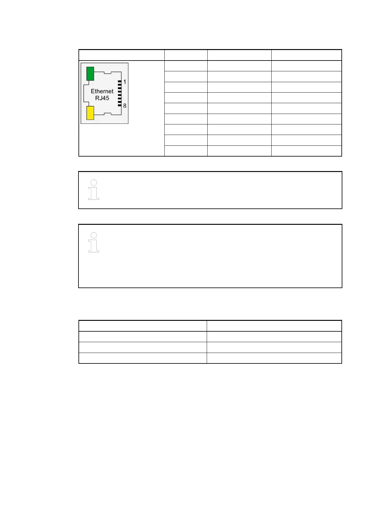
Table 136: Pin assignment RJ45 jack:
Interface Pin Signal Description
1 TxD+ Transmit data +
2 TxD- Transmit data -
3 RxD+ Receive data +
4 NC not used
5 NC not used
6 RxD- Receive data -
7 NC not used
8 NC not used
Shield Cable shield Functional earth
For further information regarding wiring and cable types see chapter Ethernet
Ä
Chapter 2.6.4.10 “Ethernet Connection Details” on page 1288.
The EtherCAT network differentiates between input-connectors (IN) and output-
connectors (OUT):
At the EtherCAT slaves (communication interface modules), the ETH1-con-
nector is IN and the ETH2-connector is OUT.
At the EtherCAT master (communication module), the ETHCAT1 connector has
to be used. The ETHCAT2 connector is reserved for future extensions.
1.7.3.2.5 Internal Data Exchange
Parameter Value
Digital inputs (bytes) 1
Digital outputs (bytes) 1
Configurable digital inputs/outputs (bytes) 1 + 1
1.7.3.2.6 Addressing
The Ethernet bus module CI512-ETHCAT does not consider the position of the rotary switches
at the front side of the module. The function of the rotary switches is reserved for future expan-
sions.
Communication Interface Modules (S500) > EtherCAT
2019/04/173ADR010121, 13, en_US864