1.7.1.2.5 Addressing
A detailed description concerning addressing can be found in the documentation of ABB Control
Builder Plus Software.
The CANopen bus module reads the position of the rotary switches only during
power-up, i. e. changes of the switch position during operation will have no
effect until the next module initialization.
The range of permitted CANopen slave addresses is 1 to 127. Setting a higher
address (> 128) does not lead to an error response, but results in a special
mode (DS401). In this special mode, the device creates the node address by
subtracting the value 128 from the address switch's value.
1.7.1.2.6 I/O Configuration
The CI582-CN CANopen bus configuration is handled by CANopen master with the exception of
the slave node ID (via rotary switches) and the baud rate (automatic detection).
The digital I/O channels and the fast counter are configured via software.
1.7.1.2.7 Parameterization
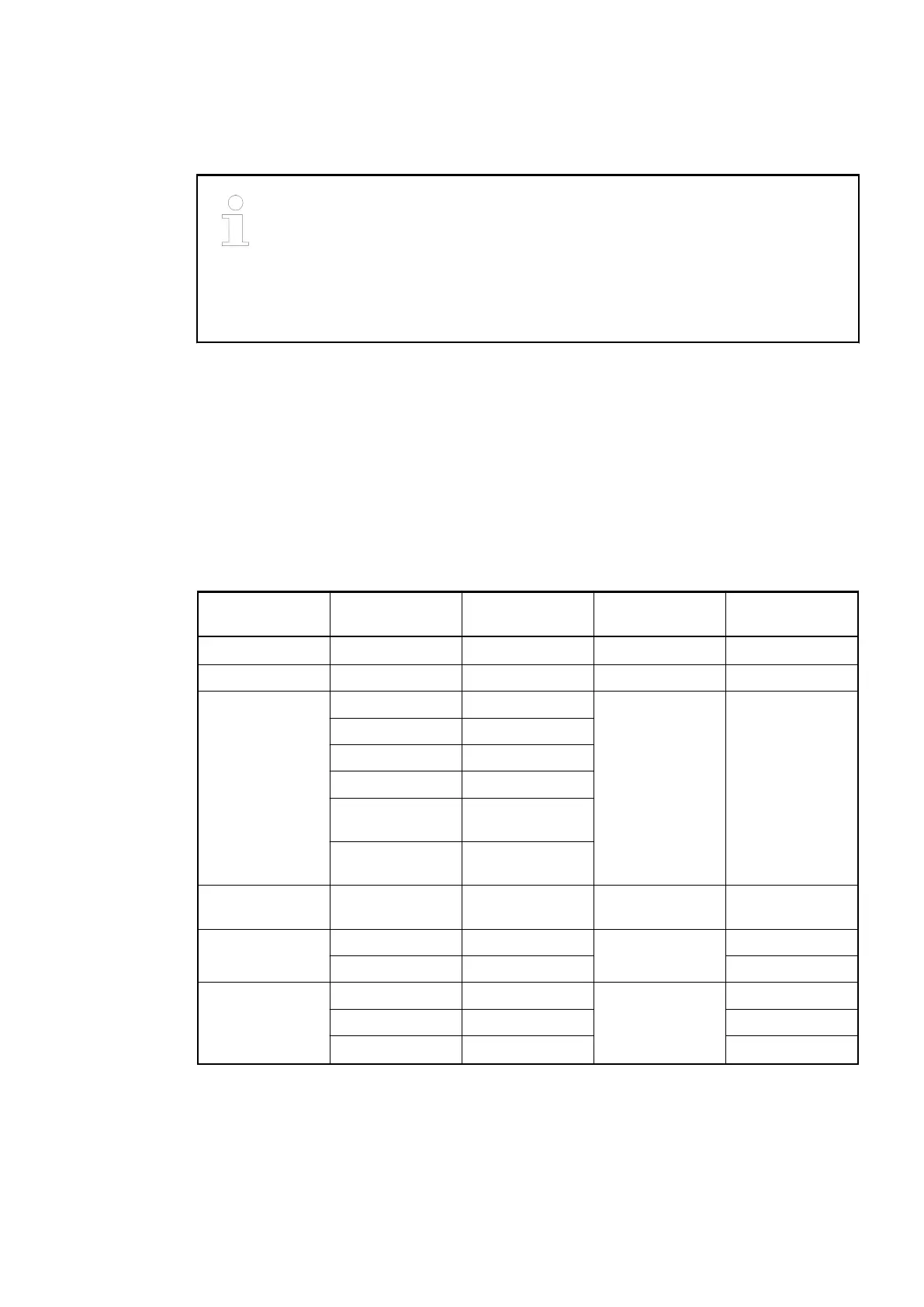
Parameters of the Module
Name Value Internal value Internal value,
type
Default
Module ID
1
)
Internal 0x1C84 WORD 0x1C84
Parameter length Internal 54 BYTE 54
Error LED / Fail-
safe function
(table error LED /
Failsafe function
Ä
Further infor-
mation
on page 721)
On 0 BYTE 0
Off by E4 1
Off by E3 2
On + failsafe 16
Off by E4 + fail-
safe
17
Off by E3 + fail-
safe
18
Reserved 0 0 ARRAY of 24
BYTES
Check supply
(UP and UP3)
On 0 BYTE
Off 1 1
Fast counter 0 0 BYTE 0
: :
10
2
)
10
1
) With a faulty ID, the Modules reports a "parameter error" and does not perform cyclic process
data transmission
2
) For a description of the counter operating modes, please refer to the Fast Counter section.
Communication Interface Modules (S500) > CANopen
2019/04/17 3ADR010121, 13, en_US 721