NOTICE!
Risk of damaging the PLC modules!
Overvoltages and short circuits might damage the PLC modules.
– Make sure that all voltage sources (supply and process voltage) are
switched off before you begin with operations at the system.
– Never connect any voltages or signals to reserved terminals (marked with
---). Reserved terminals may carry internal voltages.
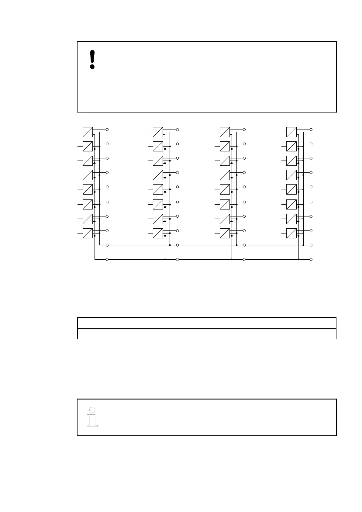
The following block diagram shows the internal construction of the digital outputs:
4.0 O 24
4.1 O 25
4.2 O 26
4.3 O 27
4.4 O 28
4.5 O 29
4.6 O 30
4.7 O 31
4.9
4.8
1.0 O 0
1.1 O 1
1.2 O 2
1.3 O 3
1.4 O 4
1.5 O 5
1.6 O 6
1.7 O 7
1.9
1.8
ZP 0 V
UP +24 V
2.0 O 8
2.1 O 9
2.2 O 10
2.3 O 11
2.4 O 12
2.5 O 13
2.6 O 14
2.7 O 15
2.9
2.8
3.0 O 16
3.1 O 17
3.2 O 18
3.3 O 19
3.4 O 20
3.5 O 21
3.6 O 22
3.7 O 23
3.9
3.8
The module provides several diagnosis functions
Ä
Chapter 1.5.1.2.6.7 “Diagnosis”
on page 357.
Internal Data Exchange
Digital inputs (bytes) 0
Digital outputs (bytes) 4
I/O Configuration
The module itself does not store configuration data. It receives its parameterization data from
the master device of the I/O bus (CPU or bus module) during power-up of the system.
Hence, replacing I/O modules is possible without any re-parameterization via software.
If the external power supply voltage via UP/ZP terminals fails, the I/O module
loses its configuration data. The whole station has to be switched off and on
again to re-configure the module.
I/O Modules > Digital I/O Modules
2019/04/17 3ADR010121, 13, en_US 355