The meaning of the LEDs is described in Displays
Ä
Chapter 1.7.5.2.9 “State LEDs”
on page 997.
Connection of the Digital Outputs
The following figure shows the electrical connection of the digital output DO8. Proceed with the
digital outputs DO9 - DO15 in the same way.
4.0
DO8
4.1
DO9
4.2
DO10
4.3
DO11
4.4
DO12
4.5
DO13
4.6
DO14
4.7
DO15
4.8
UP
4.9
ZP
24 V DC
-
+
The meaning of the LEDs is described in Displays
Ä
Chapter 1.7.5.2.9 “State LEDs”
on page 997.
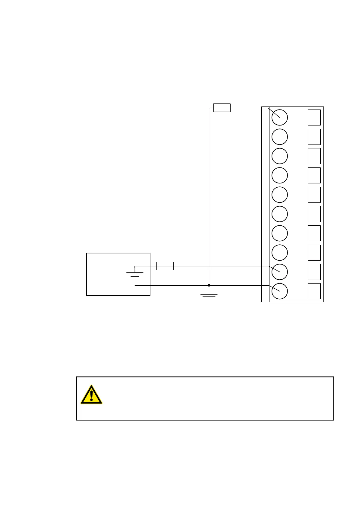
Connection of the Configurable Digital Inputs/Outputs
The following figure shows the electrical connection of the configurable digital input/output DC0
and DC1. DC0 is connected as an input and DC1 is connected as an output. Proceed with the
configurable digital inputs/outputs DC2 to DC7 in the same way.
CAUTION!
If a DC channel is used as input, the source for the input signals should be the
impressed UP3 of the device
Ä
Chapter 1.7.5.2.3 “Electrical Connection”
on page 982.
Communication Interface Modules (S500) > PROFIBUS
2019/04/17 3ADR010121, 13, en_US 989