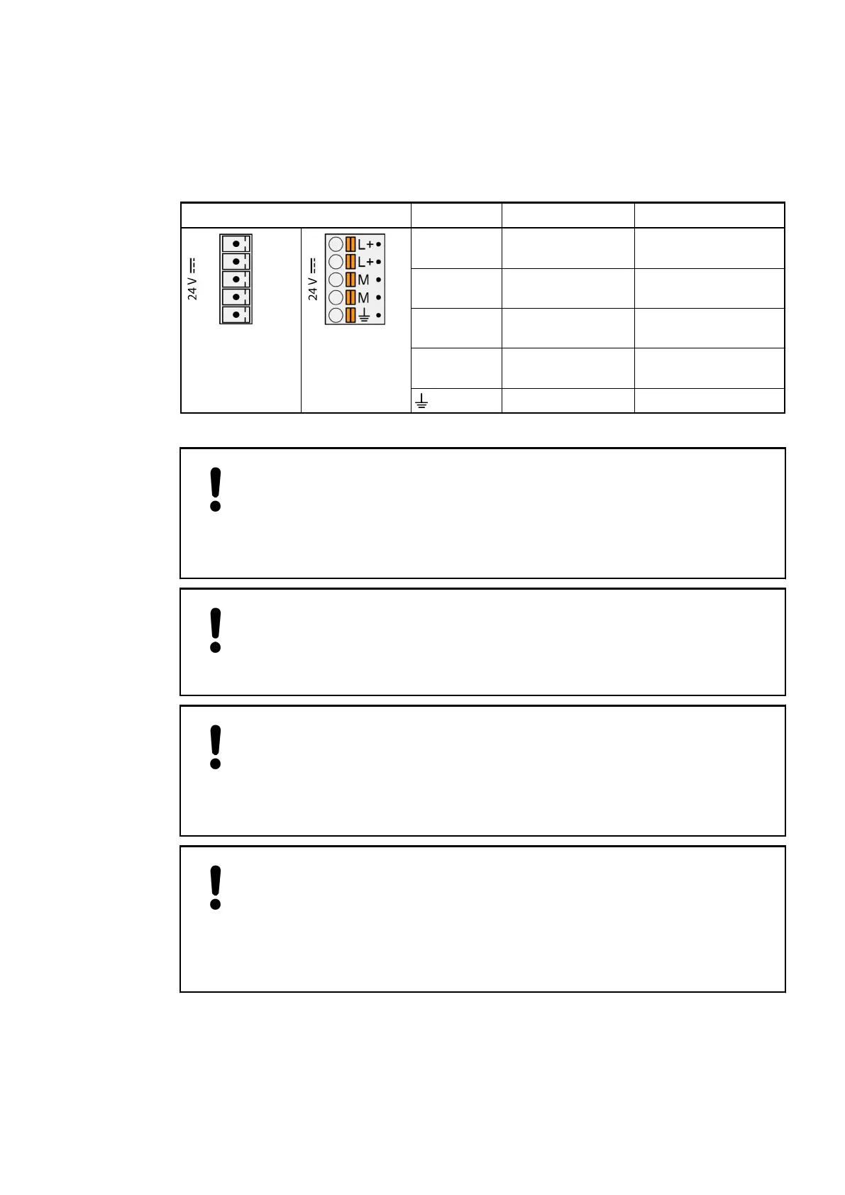
Power Supply
The supply voltage of 24 VDC is connected to a removable 5-pin terminal block. L+/M exist
twice. It is therefore possible to feed e.g. external sensors (up to 8 A max. with 1.5 mm
2
con-
ductor) via these terminals.
Pin assignment Label Function Description
Terminal block
removed
Terminal block
inserted
L+ +24 VDC Positive pin of the
power supply voltage
L+ +24 VDC Positive pin of the
power supply voltage
M 0 V Negative pin of the
power supply voltage
M 0 V Negative pin of the
power supply voltage
FE Functional earth
NOTICE!
Risk of damaging the processor module and terminal base!
Exceeding the maximum voltage could lead to unrecoverable damage to the
system.
The system could be destroyed.
NOTICE!
Risk of malfunction!
To ensure reliability and proper functionality, the supply voltage must ramp-up
from 0 V to 24 V within max. 2.5 s
NOTICE!
Risk of damaging the terminal base and power supply!
Short circuits might damage the terminal base and power supply.
Make sure that the four clamps L+ and M (two of each) are not wrongly con-
nected (e. g. +/- of power supply is connected to both L+/L+ or both M/M)
NOTICE!
Risk of damaging the terminal base!
Terminal base can be damaged by connecting the power supply terminal block
(L+/M) to COM1.
Make sure that the COM1 terminal block is always connected to the terminal
base even if you do not use COM1 to prevent this.
Pin assignment
Processor Modules > AC500 (Standard)
2019/04/17 3ADR010121, 13, en_US 83