The System Data of AC500-XC
Ä
Chapter 2.7.1 “System Data AC500-XC” on page 1309 are
valid for the XC version.
Only additional details are therefore documented below.
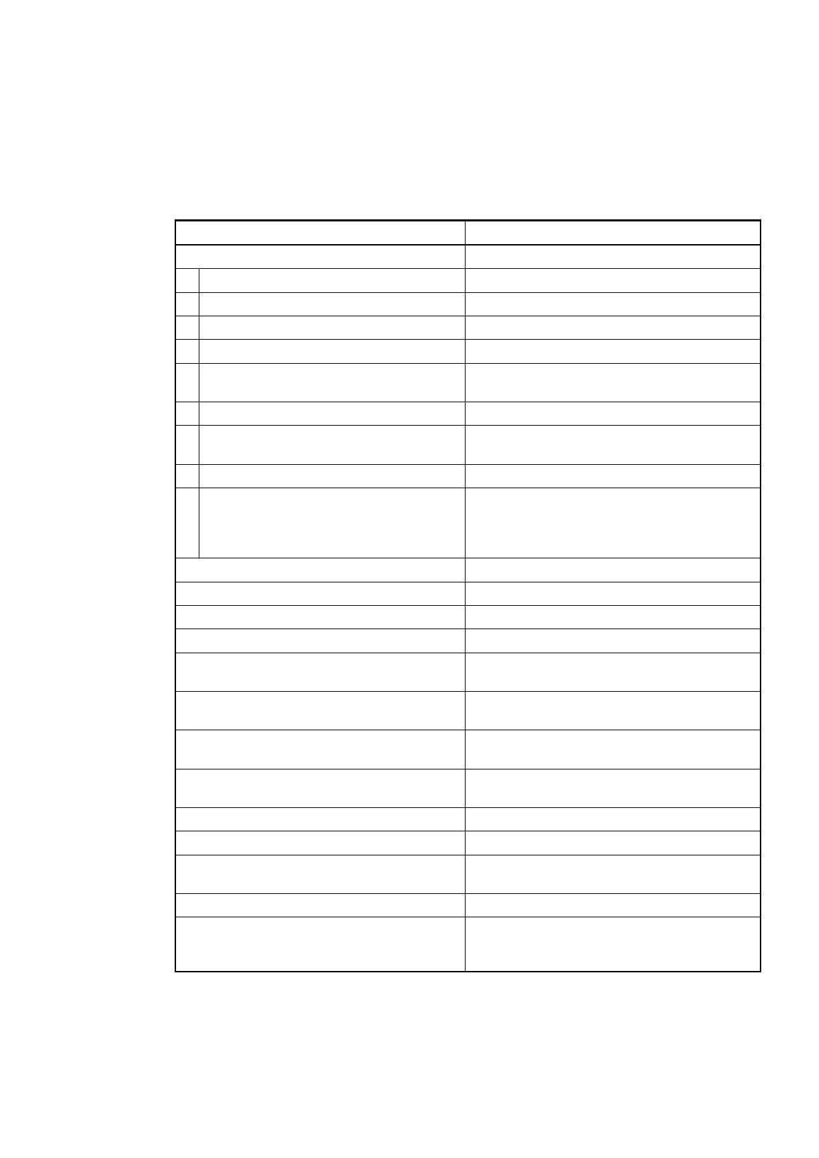
Technical Data of the Module
Parameter Value
Process supply voltages UP/UP3
Rated value 24 VDC (for inputs and outputs)
Max. load for the terminals 10 A
Protection against reversed voltage Yes
Rated protection fuse on UP/UP3 10 A fast
Electrical isolation Ethernet interface against the rest of the
module
Inrush current from UP (at power up) On request
Current consumption via UP (normal
operation)
0.15 A
Current consumption via UP3 0.06 A + 0.5 A max. per output
Connections Terminals 1.8 and 2.8 for +24 V (UP)
Terminal 3.8 for +24 V (UP3)
Terminals 1.9, 2.9 and 3.9 for 0 V (ZP)
Max. power dissipation within the module 6 W
Number of digital inputs 8
Number of digital outputs 8
Number of configurable digital inputs/outputs 8
Reference potential for all digital inputs and
outputs
Minus pole of the supply voltage, signal name
ZP
Ethernet 10/100 base-TX, internal switch, 2 x RJ45
socket
Setting of the IO Device identifier With 2 rotary switches at the front side of the
module
Diagnosis
See Diagnosis and Displays
Ä
Chapter
1.7.4.2.8 “Diagnosis” on page 929
Operation and error displays 34 LEDs (totally)
Weight (without Terminal Unit) Ca. 125 g
Mounting position Horizontal or vertical with derating (output load
reduced to 50 % at 40°C per group)
Extended ambient temperature (XC version) > 60 °C on request
Cooling The natural convection cooling must not be
hindered by cable ducts or other parts in the
switch-gear cabinet.
Communication Interface Modules (S500) > Modbus
2019/04/173ADR010121, 13, en_US936