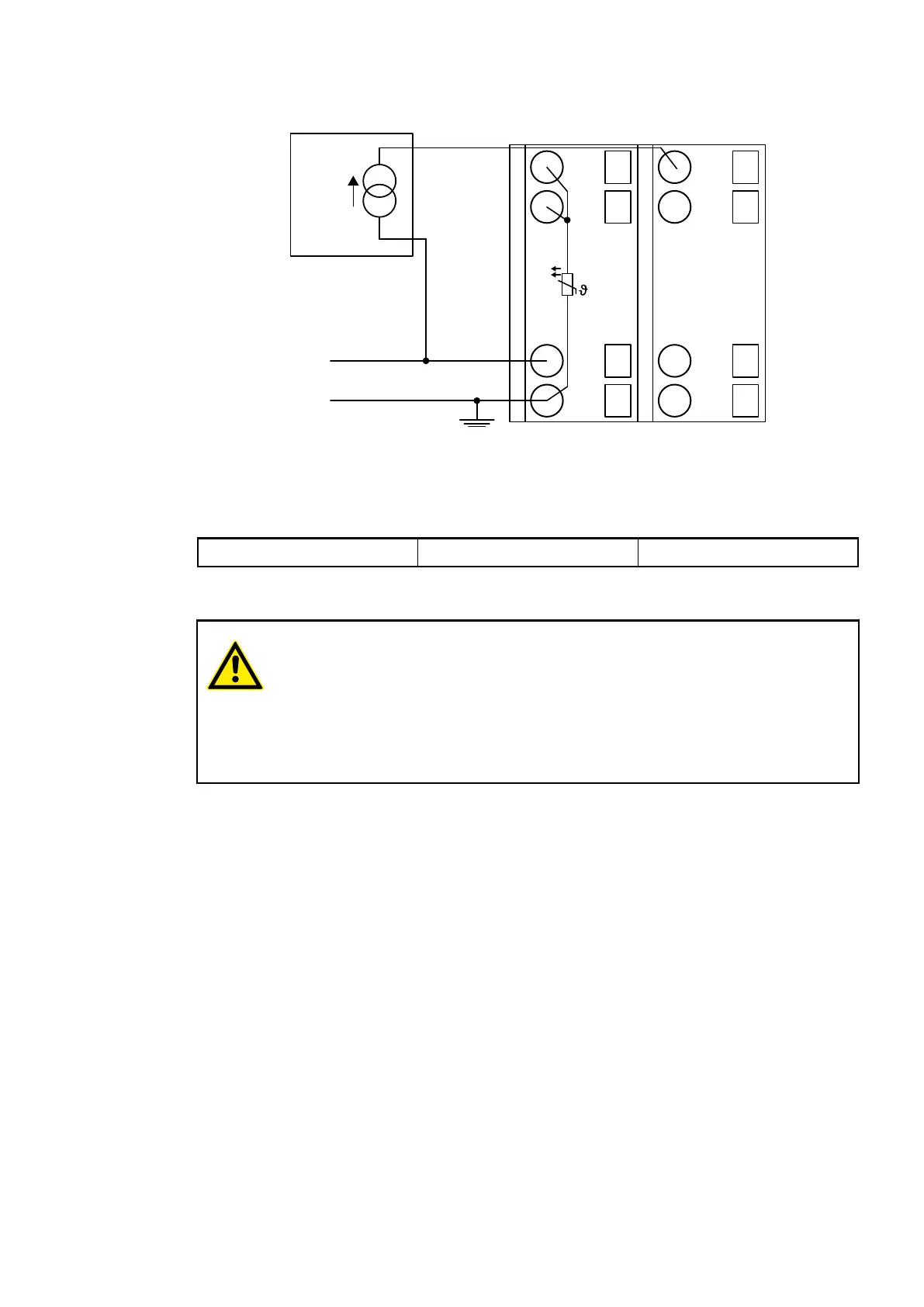
Connection of Passive-type Analog Sensors (Current)
UP
ZP
1.0
I0-
1.1
I1-
1.8
UP
1.9
ZP
PTC
2.0
I0+
2.1
I1+
2.8
UP
2.9
ZP
4 ... 20 mA
-
+
Fig. 38: Connection example
The following measuring ranges can be configured
Ä
Chapter 1.5.2.2.1.6 “Parameterization”
on page 463
Ä
Chapter 1.5.2.2.1.9 “Measuring Ranges” on page 468
Current 4 mA...20 mA 1 channel used
The function of the LEDs is described under Displays
Ä
Chapter 1.5.2.2.1.7 “Diagnosis”
on page 466.
CAUTION!
If, during initialization, an analog current sensor supplies more than 25 mA for
more than 1 second into an analog input, this input is switched off by the
module (input protection). In such cases, it is recommended to protect the
analog input by a 10 volt Zener diode (in parallel to I+ and I-). But, in general, it
is a better solution to use sensors with fast initialization or without current peaks
higher than 25 mA.
Unused input channels can be left open-circuited, because they are of low resistance.
Connection of Active-type Analog Sensors (Voltage) to Differential Inputs
Differential inputs are very useful if analog sensors which are remotely non-isolated (e.g. the
negative terminal is remotely earthed) are used.
The evaluation using differential inputs helps to considerably increase the measuring accuracy
and to avoid earthing loops.
With differential input configurations, two adjacent analog channels belong together (e.g. the
channels 0 and 1). In this case, both channels are configured according to the desired operating
mode. The lower address must be the even address (channel 0), the next higher address must
be the odd address (channel 1). The converted analog value is available at the higher address
(channel 1).
The analog value is calculated by subtraction of the input value with the higher address from the
input value of the lower address.
The converted analog value is available at the odd channel (higher address).
I/O Modules > Analog I/O Modules
2019/04/173ADR010121, 13, en_US460