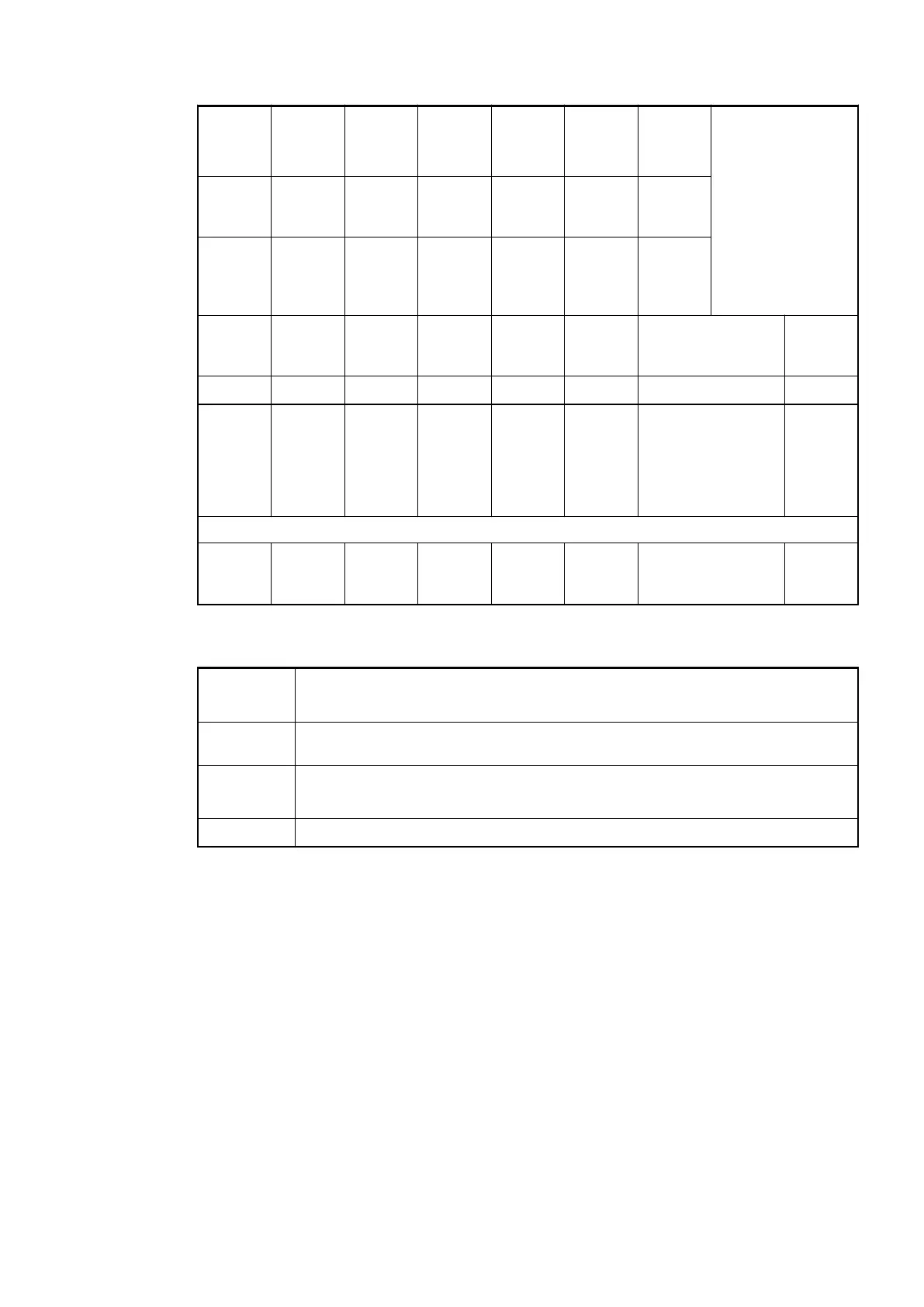
E1..E4 d1 d2 d3 d4 Identi-
fier
000..063
AC500
display
<− Display in
Class Comp Dev Mod Ch Err PS501
PLC
browser
Byte 6
Bit 6..7
- Byte 3 Byte 4 Byte 5 Byte 6
Bit 0..5
FBP
diag-
nosis
block
Class Inter-
face
Device Module Channel Error
identi-
fier
Error message Remedy
1
)
2
)
3
)
4
)
4 11 ADR 31/1.7 31 32 Wrong I/O module
in the slot
Replace
I/O
module
or check
configu-
ration
Channel error DC551-CS31
4 11 ADR 31/1..7 8..23 47 Short-circuit at a
digital output
Check
connec-
tion
Remarks:
1
)
In AC500 the following interface identifier applies:
11 = COM1 (protocol CS31 bus only possible with COM1)
2
)
With "Device" and CS31 bus master, the hardware address of the DC551-CS31
(0...69) is output.
3
)
With "Module" the following allocation applies:
31 = Module itself, 1...7 = Expansion 1...7
4
)
In case of module errors, with channel "31 = Module itself" is output.
1.7.2.3.12 Status LEDs
The LEDs are on the front panels of the modules. There are two different groups:
● The 4 system LEDs (PWR, S-ERR, CS31 and I/O-Bus) show the operating status of the
module and indicate possible errors.
● The 28 process LEDs (UP, inputs, outputs, CH-ERR2 to CH-ERR4) display the supply
voltage and signal statuses of the inputs and outputs and indicate possible errors.
All of the S500 modules have LEDs to display operating statuses and errors.
Communication Interface Modules (S500) > CS31
2019/04/17 3ADR010121, 13, en_US 821